Lens apparatus and image-taking system with multiple focus modes

a technology of image-taking system and lens apparatus, which is applied in the field of lens apparatus used in image-taking system, can solve the problems of user not being able to intentionally adjust the focus state from the outside, and the apparatus is not able to be used

Inactive Publication Date: 2008-10-28
CANON KK
View PDF7 Cites 26 Cited by
  • Summary
  • Abstract
  • Description
  • Claims
  • Application Information

AI Technical Summary

Problems solved by technology

However, this lens apparatus is not the hybrid focus-type lens apparatus with the front focusing lens unit and rear focusing lens unit.
Furthermore, in the hybrid focus-type lens apparatus disclosed in Japanese Laid-Open Patent Application No. 2003-344750, the user cannot intentionally adjust the focus state from the outside of the apparatus since the front focusing lens unit and the operating member are fixed in the AF mode.
Therefore, there is a problem that, for example, the AF functions on a front person in a focusing area though the user wants the AF to function on a back wall for camera effects.

Method used


Image

  • Lens apparatus and image-taking system with multiple focus modes
  • Lens apparatus and image-taking system with multiple focus modes
  • Lens apparatus and image-taking system with multiple focus modes

Examples


embodiment 1

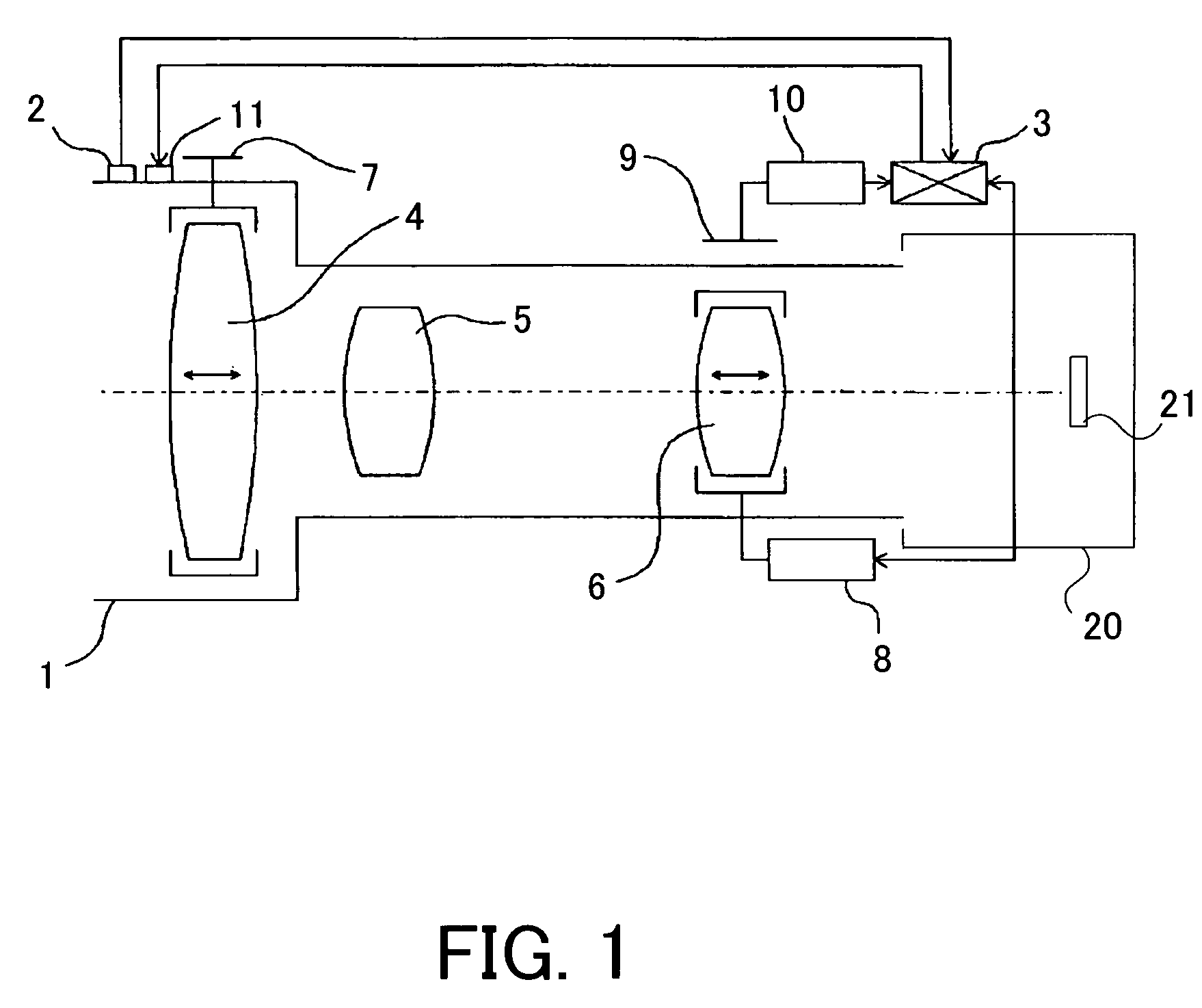
[0017]FIG. 1 shows the structure of a lens apparatus in Embodiment 1 of the present invention, which has focusing lens units for AF and MF.

[0018]In FIG. 1, the reference numeral 1 denotes the lens apparatus, the reference numeral 2 denotes a mode selection switch for selecting a focus mode, and the reference numeral 3 denotes a controller (control circuit). The mode selection switch 2 is installed at an optional position on the lens apparatus 1, and the focus mode is selected by user's operation of the mode selection switch 2. The content of the selection is transmitted to the controller 3.

[0019]In this embodiment, the focus mode can be selected from three modes, which are a manual focus (MF) mode as a first mode, an automatic focus (AF) mode and an AF assist mode. In the AF assist mode, the MF operation (MF sub-mode) can be performed at any time during the AF operation (AF sub-mode), and thereby the user can adjust the focus state intentionally. Herein, the AF sub-mode in the AF as...

embodiment 2

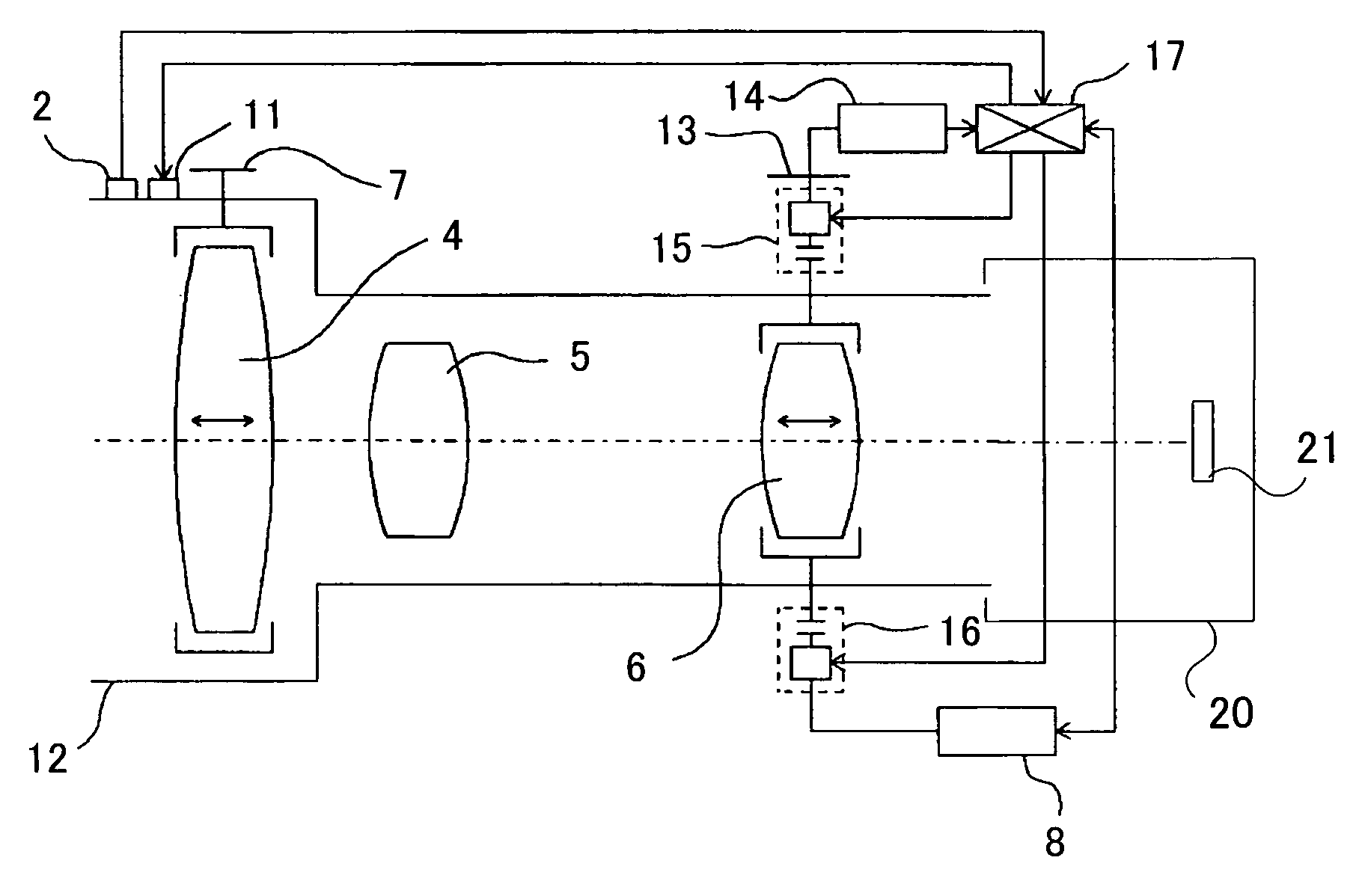
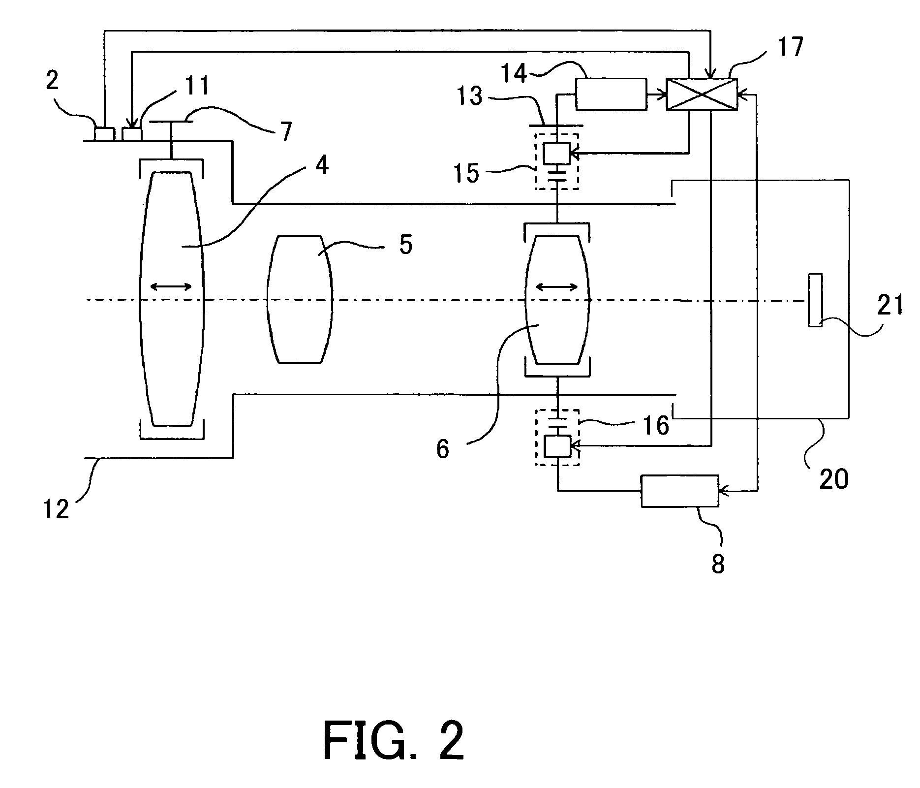
[0047]FIG. 2 shows the structure of a lens apparatus in Embodiment 2 of the present invention, which has focusing lens units for AF and MF.

[0048]In FIG. 2, the reference numeral 12 denotes the lens apparatus, the reference numeral 2 denotes a mode selection switch for selecting a focus mode, and the reference numeral 17 denotes a controller (control circuit). The mode selection switch 2 is installed at an optional position on the lens apparatus 1 as well as Embodiment 1, and the focus mode is selected by user's operation of the mode selection switch 2. The content of the selection is transmitted to the controller 17.

[0049]In the lens system of this lens apparatus 12, in order from the object side (the left side in the figure), the reference numeral 4 denotes a front focusing lens unit driven in the MF mode, the reference numeral 5 denotes a magnification-varying lens unit, and the reference numeral 6 denotes a rear focusing lens unit driven in the AF mode and AF sub-mode.

[0050]The r...


PUM


Abstract

A lens apparatus is disclosed, in which the MF operation can be performed at any time during the AF operation. The lens apparatus comprises a lens system including a front focusing lens, a magnification-varying lens and a rear focusing lens, a first operating member, and a second operating member. The front focusing lens is driven for manual focus in accordance with the operation of the first operating member in the first mode, the rear focusing lens is driven for automatic focus in the second mode. The focus mode is switched from the second mode to the third mode in accordance with the operation of the second operating member. The rear focusing lens is driven in accordance with the operation of the second operating member in the third mode.

Description

FIELD OF THE INVENTION[0001]The present invention relates to a lens apparatus used for an image-taking system, especially a lens apparatus used for a television camera system and video camera system equipped with automatic focus and manual focus.[0002]Conventionally, so-called hybrid focus-type lens apparatuses are known as lens apparatuses equipped with an automatic focus function and used with cameras such as television cameras or video cameras, which are disclosed in Japanese Laid-Open Patent Application No. 2003-344750, for example.[0003]In the hybrid focus-type lens apparatus, a rear focusing lens for automatic focus (hereafter, it is referred to as AF) is driven in AF mode, a front focusing lens for manual focus (hereafter, it is referred to as MF) is driven in MF mode.[0004]As shown in FIG. 4, the hybrid focus-type lens apparatus is equipped with a rear focusing lens unit 106 for AF and a front focusing lens unit 104 for MF, and is used for image-taking in two focus modes, wh...

Claims


Application Information

Patent Timeline
Patent Type & Authority Patents(United States)
IPC IPC(8): H04N5/232G02B7/10G02B7/28
CPCG02B7/102
Inventor HIRAOKA, AKIRA
Owner CANON KK
Why Eureka
Try Eureka