
Vehicle backward movement detection apparatus and vehicle braking force control apparatus

a detection apparatus and vehicle technology, applied in the direction of braking systems, instruments, analogue processes for specific applications, etc., can solve the problems of difficult to accurately measure the speed of the wheel and take a long time for the vehicle body speed to reach the predetermined speed, and achieve the effect of accurately controlling the braking for

Active Publication Date: 2008-10-28
TOYOTA JIDOSHA KK
View PDF9 Cites 11 Cited by
  • Summary
  • Abstract
  • Description
  • Claims
  • Application Information

AI Technical Summary

Benefits of technology

[0007]It is thus an object of this invention to provide a vehicle backward movement detection apparatus capable of detecting backward movement of a vehicle on a hill and a vehicle braking force control apparatus capable of accurately controlling a braking force even when the vehicle body speed is low.
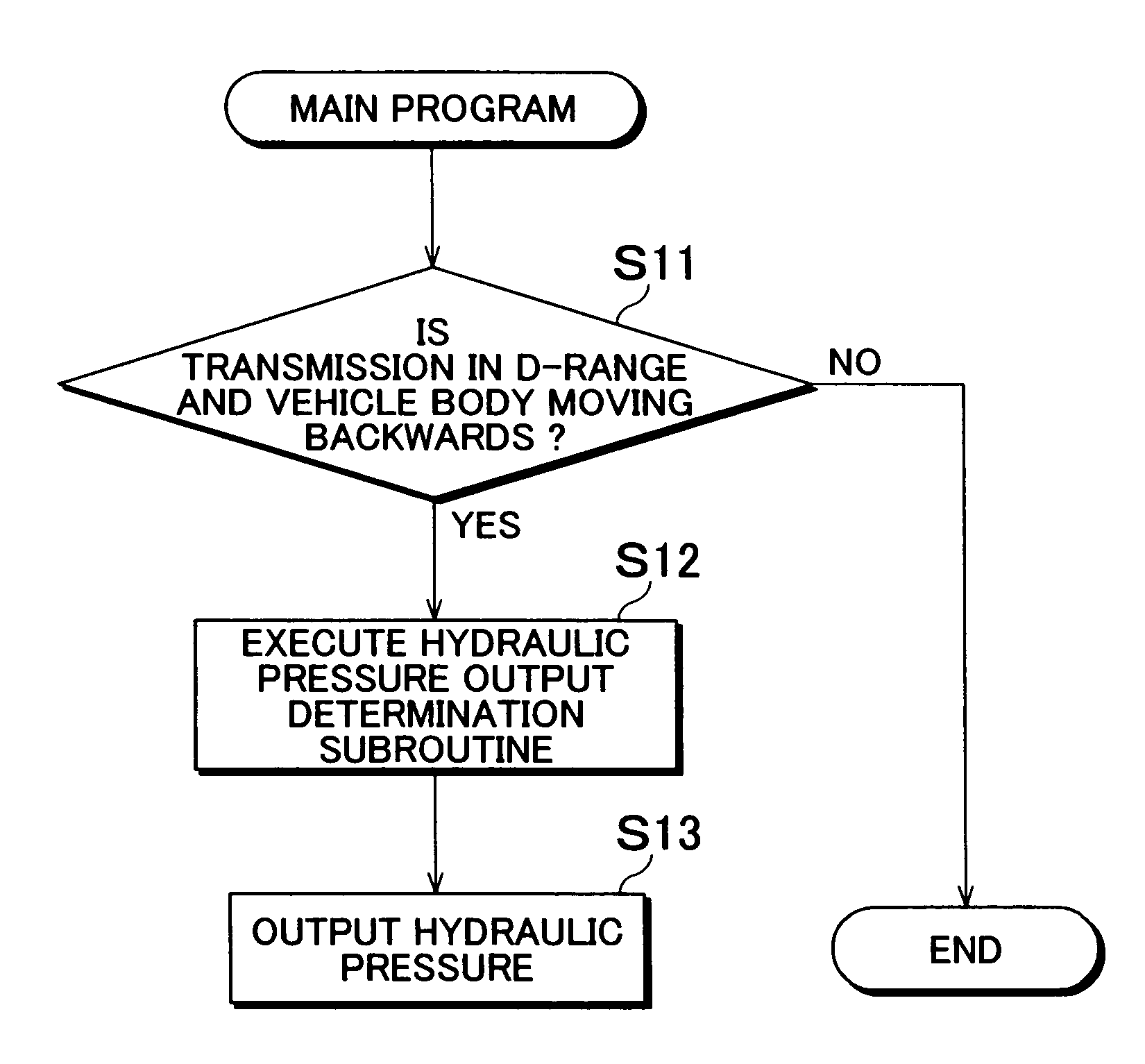
[0015]According to the first aspect and the modification of that first aspect, an initial value of the brake output may be set smaller when a period of time detected by the time detecting device is longer than a predetermined period of time than it is when the period of time detected by the time detecting device is shorter than the predetermined period of time. That is, when this period of time is long it means that the gradient of the hill is small, so it is preferable to set the brake output small so that braking is performed gently and smoothly. When that period of time is short, on the other hand, it means that the gradient of the hill is large, so the brake output is set relatively large so that braking can be performed quickly.
[0017]The vehicle braking force control apparatus according to the first aspect and the modification of that first aspect, the brake device may be provided on each of front and rear wheels of the vehicle, and the brake output determining device determine the brake output so that the braking force of the brake devices on the rear wheels is set higher than the braking force of the brake devices on the front wheels when the period of time is longer than the predetermined period of time than when the period of time is shorter than the predetermined period of time. Accordingly, when the vehicle moves backwards on a hill, the period of time decreases the steeper the gradient and more load is placed on the rear wheels than on the front wheels. Making the braking force of the brake devices on the rear wheels relatively high therefore enables the vehicle to be effectively brought to a stop.
[0019]According to the first aspect and the modification of that first aspect, the brake output determining device may determine the brake output such that the braking force is prohibited from being cancelled from the time the braking force is applied until a fixed period of time passes or until an accelerator operation is performed. That is, a control that cancels the braking force immediately after the vehicle has stopped was conventionally proposed, but in this case, hunting would occur, with the control fluctuating between applying braking force (thus stopping the vehicle) and canceling the braking force (resulting in the vehicle moving backwards).
[0022]According to the first aspect and the modification of that first aspect, the brake output determining device may determine the brake output so that the braking force is maintained when the vehicle body speed is equal to, or less than, the first vehicle body speed and greater than a second vehicle body speed after the initial value for the braking output has been determined. In this case, the first vehicle body speed is a speed in the backward direction that is faster than the second vehicle body speed. That is, because the vehicle body speed is equal to, or less than, the first vehicle body speed, the vehicle body does not need to be stopped quickly, and because it is greater than the second vehicle body speed, the braking force should not be cancelled. In this case, therefore, the brake output is determined so that the braking force is maintained.
[0025]The vehicle braking force control apparatus and vehicle backward movement detection apparatus according to this invention thus enables the braking force to be accurately controlled even when the vehicle body speed is low.

Problems solved by technology

Because the vehicle body speed when the vehicle first starts to move is low, it is often difficult to measure accurately with a wheel speed sensor.
On the other hand, if the gradient of the hill is gentle, it will probably take time for the vehicle body speed to reach the predetermined speed once the braking force is cancelled.

Method used


Image

  • Vehicle backward movement detection apparatus and vehicle braking force control apparatus
  • Vehicle backward movement detection apparatus and vehicle braking force control apparatus
  • Vehicle backward movement detection apparatus and vehicle braking force control apparatus

Examples


Embodiment Construction

[0036]In the following description and the accompanying drawings, the vehicle braking force control apparatus and vehicle backward movement detection apparatus will be described in more detail in terms of exemplary embodiments. In the description, like elements will be denoted by like reference numerals and redundant descriptions thereof will be omitted.

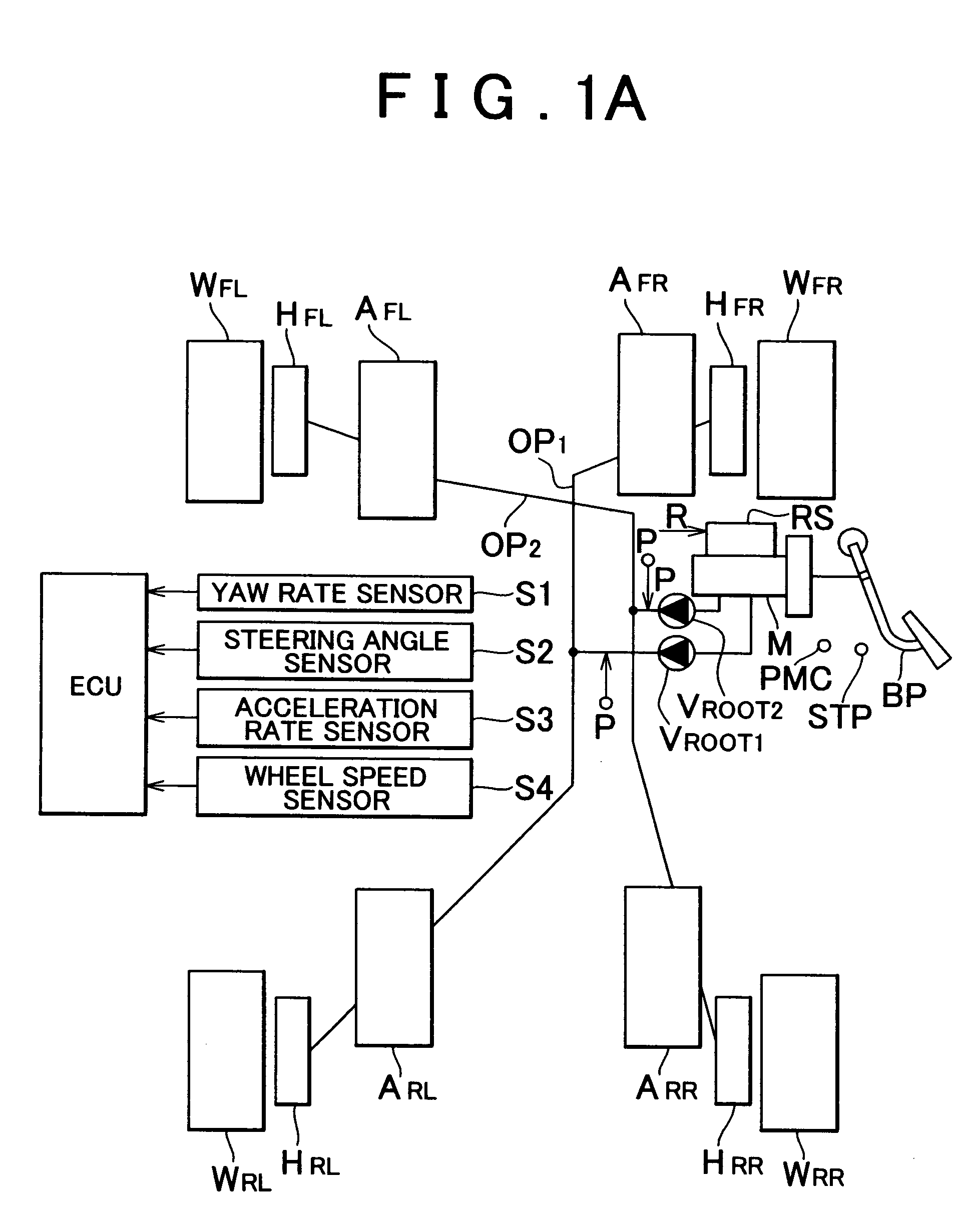
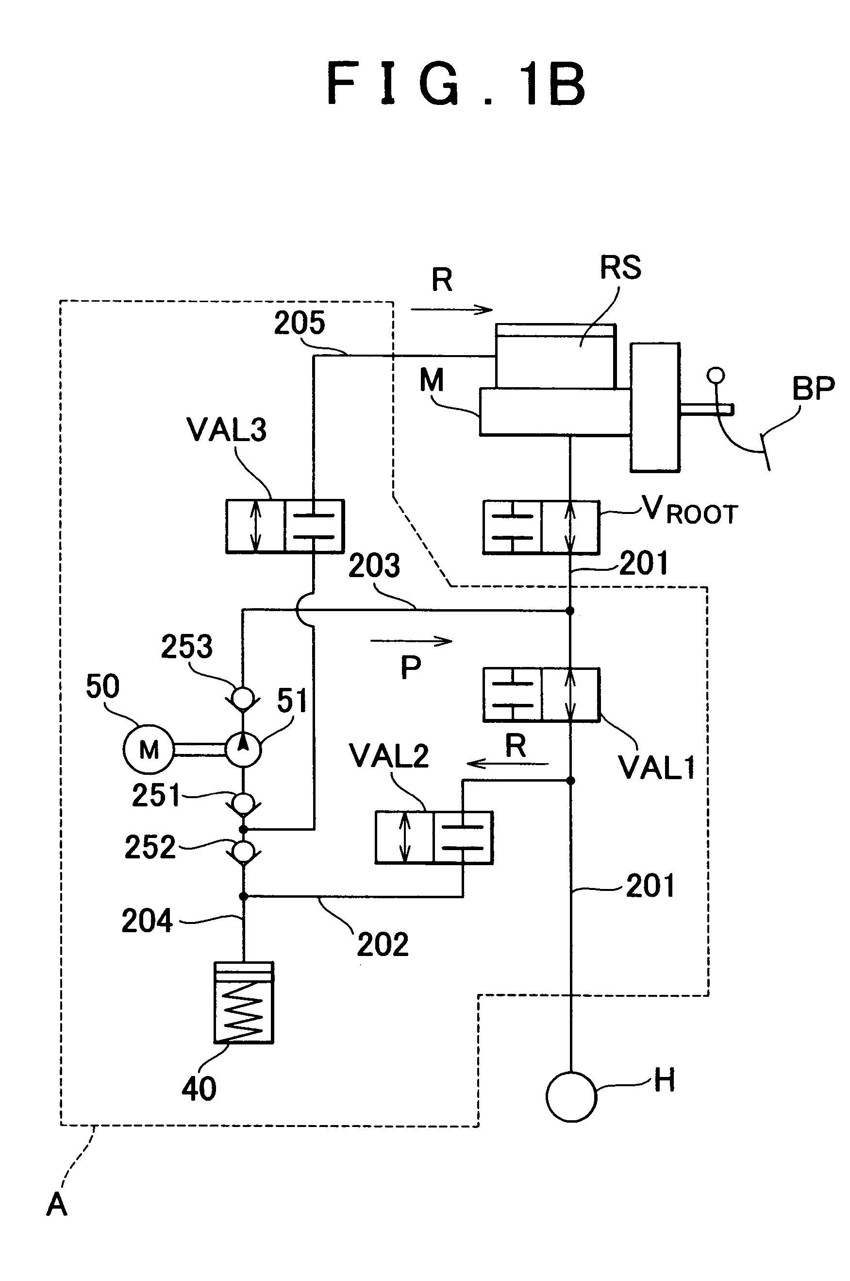
[0037]FIG. 1A is a block view of a vehicle provided with a behavior control apparatus for a vehicle according to an exemplary embodiment. FIG. 1B is a detailed view of a hydraulic pressure control valve mechanism A (=AFL, AFR, ARL, and ARR) shown in FIG. 1A.

[0038]The vehicle is provided with two front wheels WFL and WFR and two rear wheels WRL and WRR on the vehicle body. Each wheel WFL, WFR, WRL, and WRR is provided with a corresponding wheel cylinder H (=HFL, HFR, HRL, and HRR) (brake device). The wheel cylinders HFL, HFR, HRL, and HRR are all connected to a master cylinder M via hydraulic pressure passages. A brake pedal BP is lin...


PUM


Abstract

A vehicle braking force control apparatus detects a period of time from when a braking force of a brake device is cancelled until a vehicle body speed in the backwards direction of a vehicle on a hill reaches a predetermined state, determines a brake output according to the detected period of time, and controls braking pressure according to the determined brake output. The period of time depends on the gradient of the hill. Therefore, by determining the brake output according to this period of time, braking force control according to the gradient of the hill is made possible even at an extremely slow speed at which the vehicle speed is undetectable.

Description

INCORPORATION BY REFERENCE[0001]The disclosure of Japanese Patent Application No. 2003-400438 filed on Nov. 28, 2003 including the specification, drawings and abstract is incorporated herein by reference in its entirety.BACKGROUND OF THE INVENTION[0002]1. Field of the Invention[0003]The invention relates to a vehicle backward movement detection apparatus and a vehicle braking force control apparatus. More particularly, the invention relates to a vehicle backward movement detection apparatus which detects backward movement of a vehicle on a hill, and a vehicle braking force control apparatus which performs braking based on that detected backward movement.[0004]2. Description of the Related Art[0005]A vehicle braking force control apparatus is disclosed in Japanese Patent Application Publication No. JP-A-2002-264784, for example. This vehicle braking force control apparatus increases the braking force when a vehicle body acceleration rate is greater than a predetermined value in order...

Claims


Application Information

Patent Timeline
Patent Type & Authority Patents(United States)
IPC IPC(8): G06F7/70B60T7/12B60T8/48
CPCB60T7/122B60T8/4872
Inventor YAMADA, NORITAKAORIMOTO, TAKASHI
Owner TOYOTA JIDOSHA KK
Learn More