Valve timing control apparatus of internal combustion engine
a valve timing control and internal combustion engine technology, applied in the direction of valve details, valve arrangements, valve drives, etc., can solve the problems of substantially inoperative camshaft torque actuation mechanism of the above valve timing control apparatus, insufficient function of camshaft torque actuation mechanism, and relatively decreased transmission from the camshaft, etc., to achieve low dynamic responsiveness
- Summary
- Abstract
- Description
- Claims
- Application Information
AI Technical Summary
Benefits of technology
Problems solved by technology
Method used
Image

Examples
first embodiment
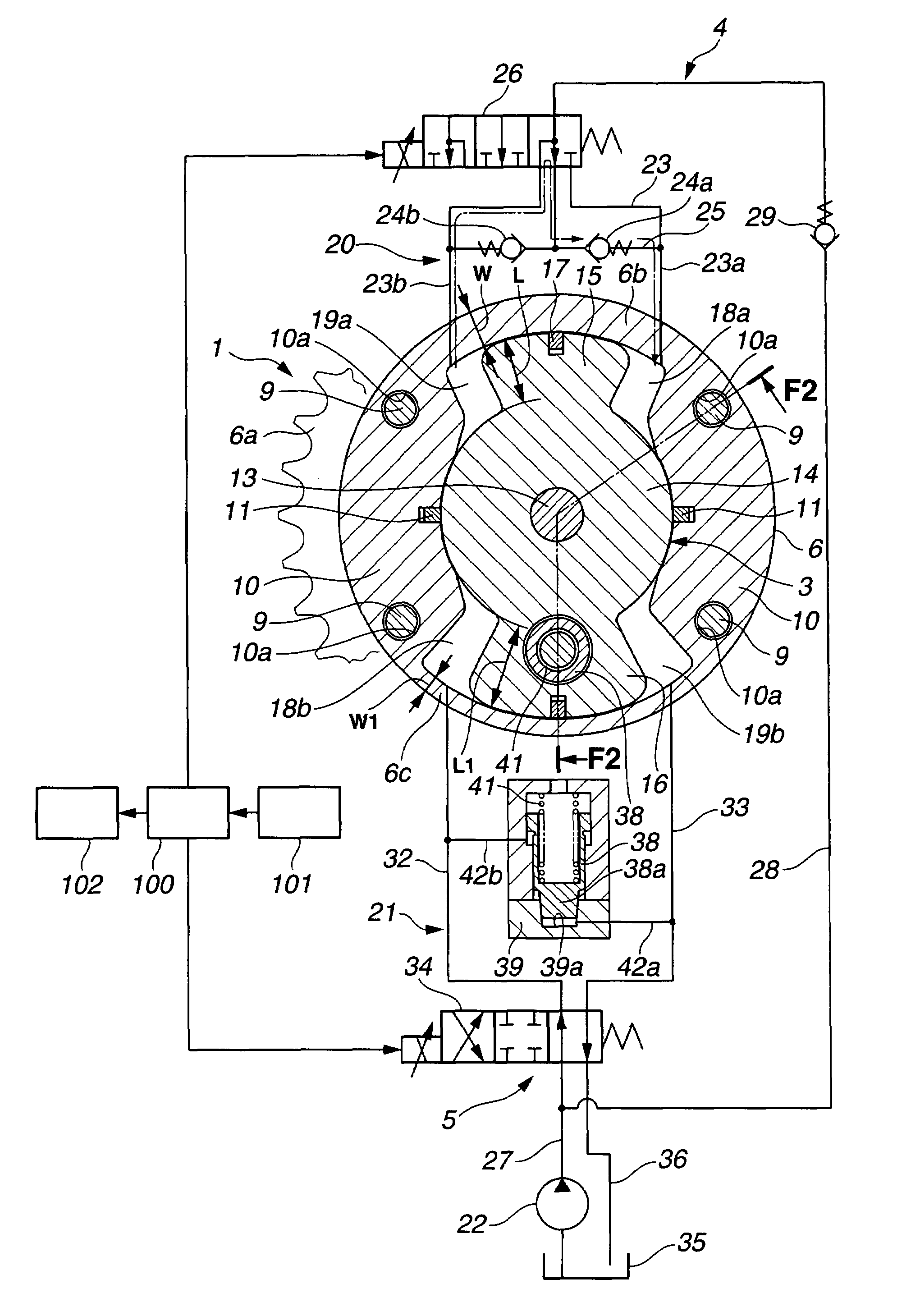
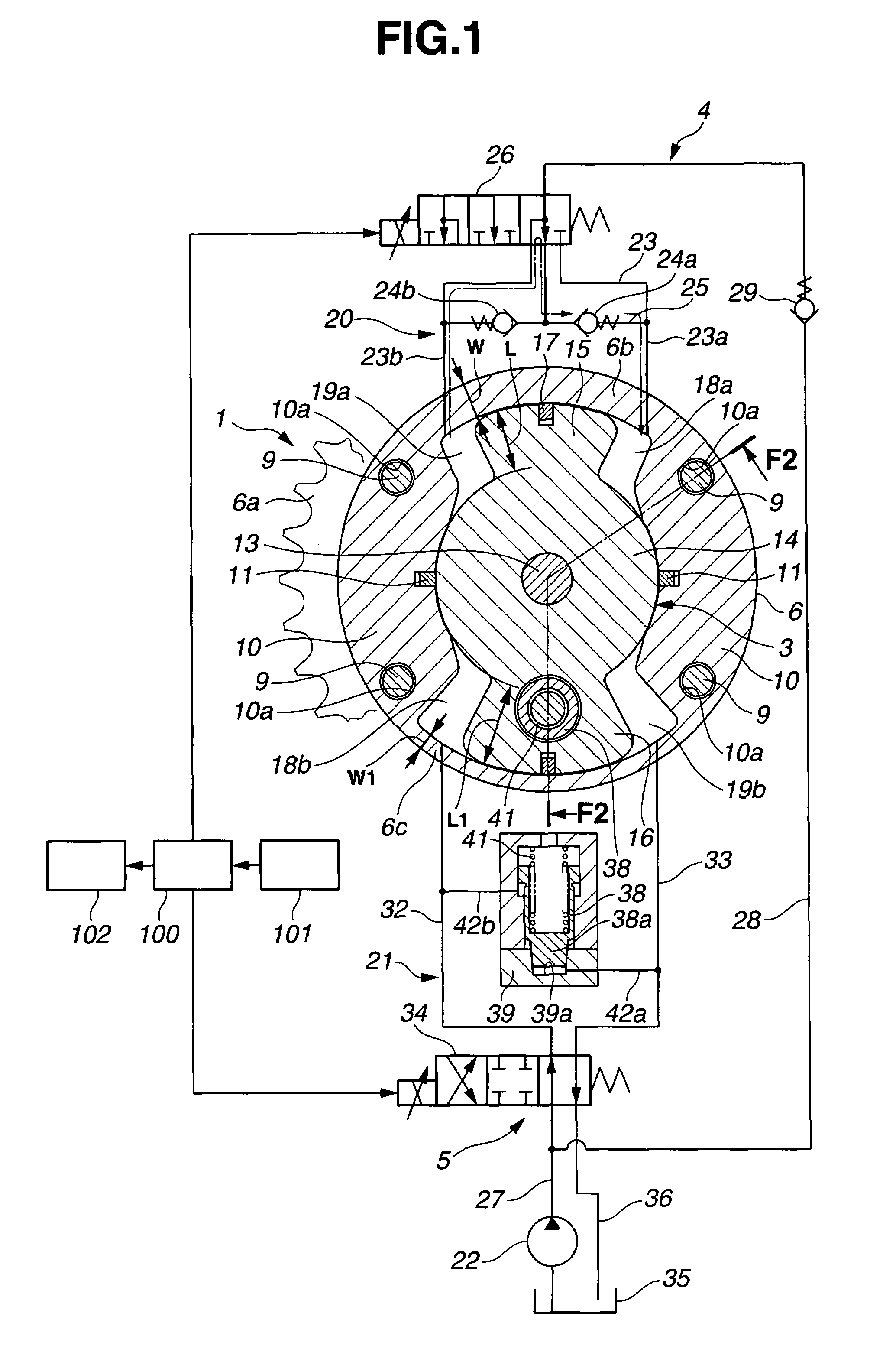
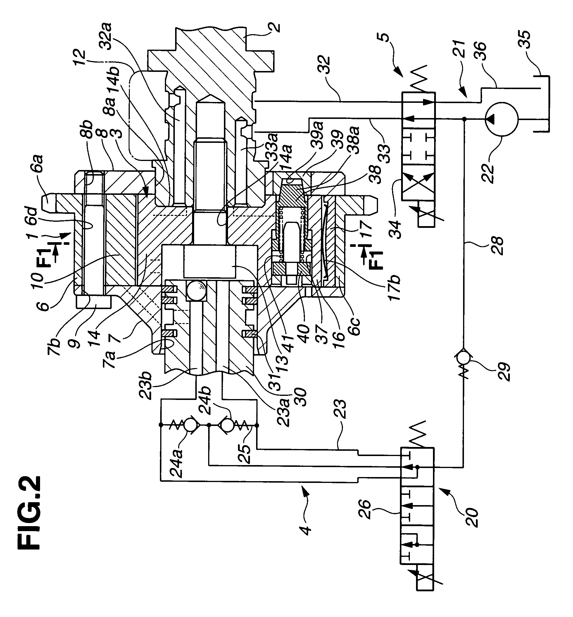
[0024]FIG. 1 shows a valve timing control apparatus or system of an internal combustion engine in accordance with the present invention. FIG. 2 shows the valve timing control apparatus in section taken along a line F2-F2 in FIG. 1 whereas FIG. 1 is a sectional view taken along a line F1-F1 shown in FIG. 2. The valve timing control apparatus of this embodiment is adapted to an exhaust valve side of the internal combustion engine.
[0025]A timing sprocket member 1 is a driving rotator which is rotated by a torque outputted from the internal combustion engine and specifically driven through a timing chain by a crankshaft of the internal combustion engine. A camshaft 2 is rotatable relative to sprocket member 1. A vane member 3 is a driven rotator which is arranged to rotate with a relative rotational phase with respect to the driving rotator and adapted to transmit the torque from the driving rotator to camshaft 2 via working fluid in a torque transmission path, and specifically fixed at...
third embodiment
[0085]FIG. 4 shows a valve timing control apparatus of an internal combustion engine in accordance with the present invention. In this example, according to the engine operating conditions, controller 100 controls each of camshaft-torque actuation mechanism 4 and hydraulic actuation mechanism 5 in a normal control mode or another different control mode.
[0086]Specifically, in the normal control mode, first directional control valve 26 and second directional control valve 34 operate similarly as in the first embodiment. For example, when the engine is in a state just prior to stop or in low speed operation, first directional control valve 26 moves the inside spool valve to the most left side in FIG. 4 to allow the working fluid to flow from first retard fluid pressure chamber 19a into first advance fluid pressure chamber 18a, to rotate vane member 3 counterclockwise in FIG. 4, and to alter the relative rotational phase of camshaft 2 with respect to timing sprocket member 1 to the most...
fourth embodiment
[0097]FIG. 6 shows a valve timing control apparatus of an internal combustion engine in accordance with the present invention. In this embodiment, first directional control valve 26 is modified to be in the form of a four-position type.
[0098]Specifically, first directional control valve 26 is controlled to be in one of a state of allowing a unidirectional flow of the working fluid from first advance fluid pressure chamber 18a to first retard fluid pressure chamber 19a, a state of allowing a unidirectional flow of the working fluid from first retard fluid pressure chamber 19a to first advance fluid pressure chamber 18a, a state shutting off fluid communication between first advance fluid pressure chamber 18a and first retard fluid pressure chamber 19a, and a state of allowing bidirectional flow between first advance fluid pressure chamber 18a and first retard fluid pressure chamber 19a.
[0099]In this embodiment, controller 100 is configured to control the relative rotational phase of...
PUM
 Abstract
Description
Claims
Application Information
 - R&D Engineer
- R&D Manager
- IP Professional
- Industry Leading Data Capabilities
- Powerful AI technology
- Patent DNA Extraction
Browse by: Latest US Patents, China's latest patents, Technical Efficacy Thesaurus, Application Domain, Technology Topic.
© 2024 PatSnap. All rights reserved.Legal|Privacy policy|Modern Slavery Act Transparency Statement|Sitemap