Sliding platform for a pick-up truck

a technology for pick-up trucks and platforms, applied in the field of sliding platforms, can solve the problems of unfavorable cargo entry, unfavorable cargo entry, and difficulty in installation of brackets,

Active Publication Date: 2008-11-04
CARGO EASE
View PDF13 Cites 23 Cited by
  • Summary
  • Abstract
  • Description
  • Claims
  • Application Information

AI Technical Summary

Problems solved by technology

Some of these devices are extremely cumbersome and difficult to install.
These brackets may be difficult to install and present unwanted intrusion into the cargo bay when the sliding platform apparatus is removed.
It is especially difficult to remove or install the sliding platform when standard bolts and nuts are used to hold the sliding apparatus in place in the cargo bay.

Method used


Image

  • Sliding platform for a pick-up truck
  • Sliding platform for a pick-up truck
  • Sliding platform for a pick-up truck

Examples


Embodiment Construction

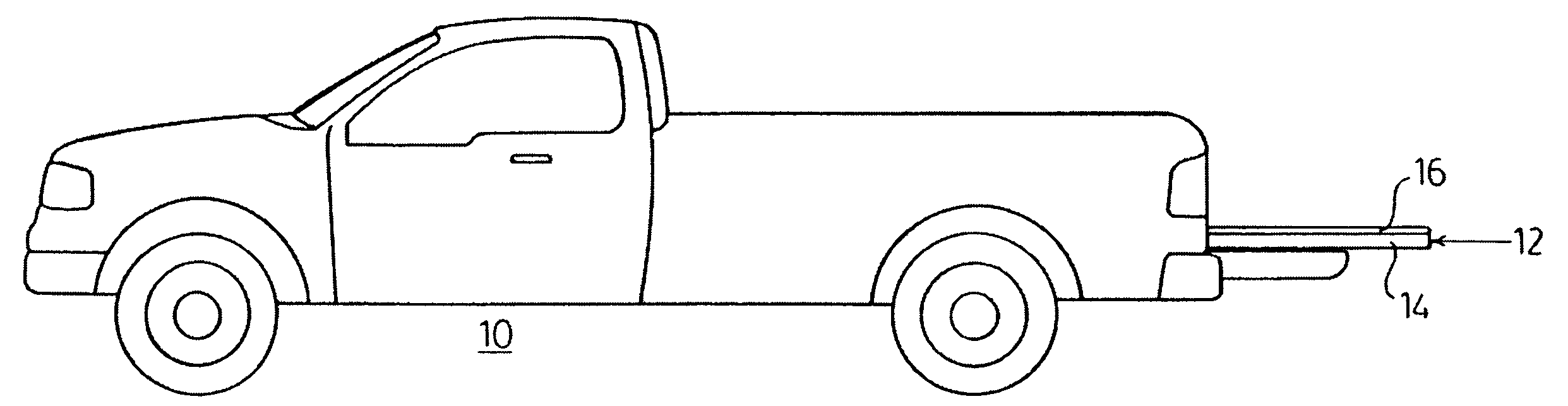
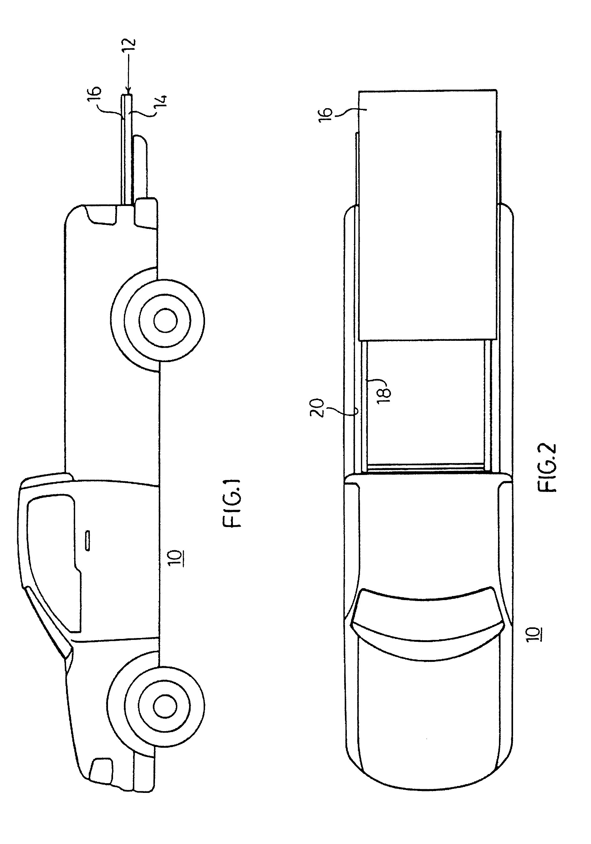
[0015]Referring now to the drawings, FIG. 1 shows an elevational view of a motor vehicle 10 having the sliding platform 12 mounted in the rear cargo space of the vehicle 10. The sliding platform comprises a sliding frame 14 to which the flat top 16 is fastened and is shown protruding from the rear of the cargo bay in its extended position.

[0016]FIG. 2 shows the same vehicle 10 in a plan view. Here platform or table 16 is shown in its extended position and the stationary frame 18 is shown mounted in cargo area 20 of vehicle 10.

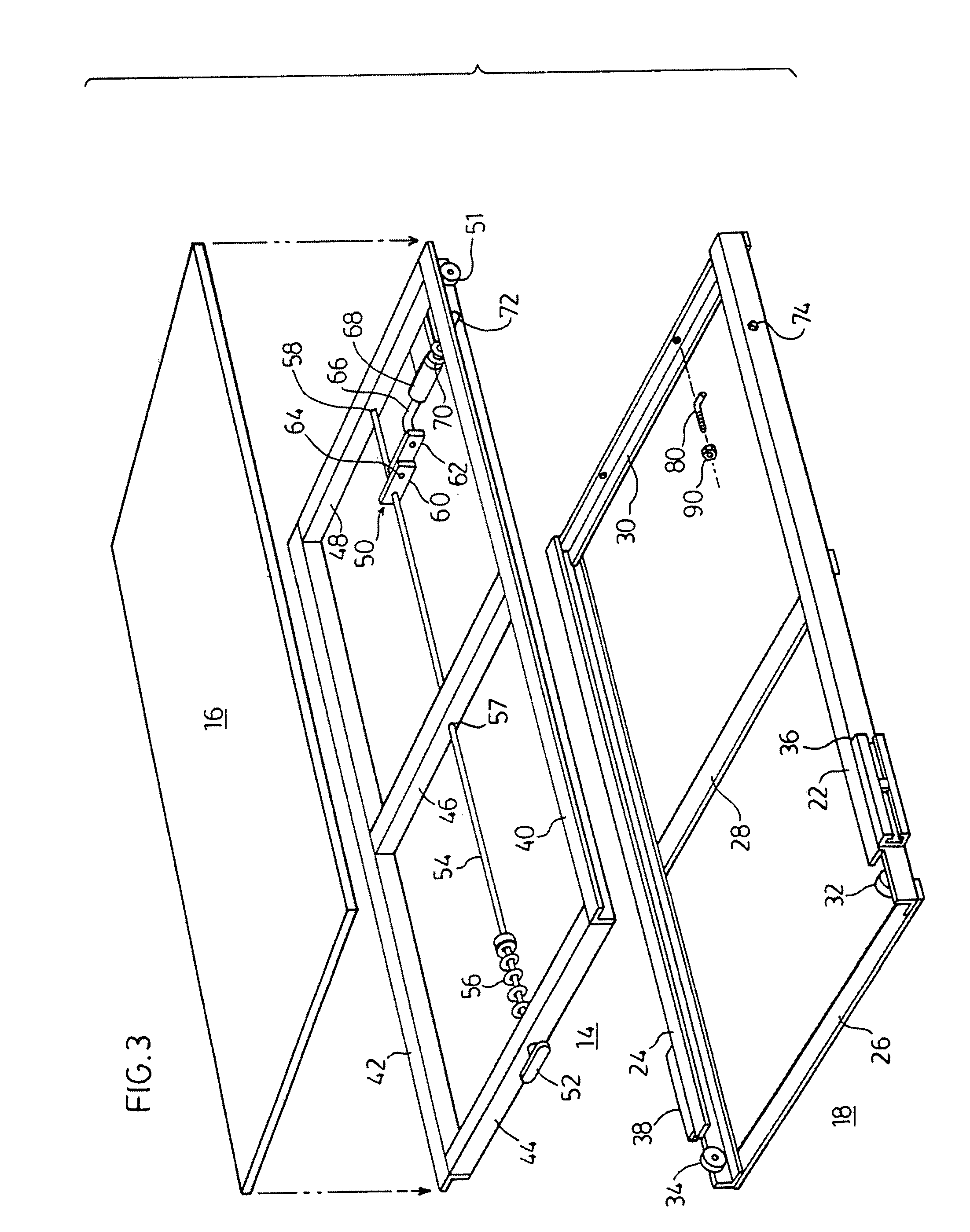
[0017]FIG. 3 shows the sliding table components in an exploded perspective view. A stationary frame 18 is shown having side channel members 22, 24 to which cross pieces 26, 28 and 30 are attached to form a unitary structure.

[0018]The side channels 22 and 24 are each supplied with low friction bearings 32 and 34 at the rear of the frame 18 for carrying the sliding frame 14 thereon. A pair of stabilizing channels 36 and 38 are securely fastened to the channels 22...


PUM


Abstract

A sliding platform is mounted on low friction rollers to cooperate with a stationary frame to produce an extending platform for the cargo area of a suitable vehicle. The stationary frame may be fastened in the cargo area of a motor vehicle by means of specially shaped bolts which attach the stationary frame to the front wall of the cargo area. The forward end of the stationary frame is therefore held in place by means of only two fastening bolts. The rearward portion of the stationary frame is located and held in place by two jackscrews which serve to engage the two opposing walls of the cargo bay.A spring loaded handle is used to unlatch the sliding platform and allow it to be slid on said stationary frame to an extended position. The spring loaded handle may be pulled out from its nested position to provide better access and gripping of the handle.

Description

FIELD OF INVENTION[0001]This invention relates to a sliding platform which is installed in the cargo bay of a modern pick up truck. The sliding platform enables the user to slide the platform rearwardly and gain access to items stored at the front of the cargo bay.BACKGROUND OF THE INVENTION[0002]Sliding platforms for cargo bays of pick up trucks have been known and used for some time (see U.S. Pat. No. 4,824,158 dated Apr. 25, 1989). Some of these devices are extremely cumbersome and difficult to install. Others require the installation of special brackets to hold the sliding apparatus in place in the cargo bay. These brackets may be difficult to install and present unwanted intrusion into the cargo bay when the sliding platform apparatus is removed. Other installations require partial disassembly of the sliding apparatus when it is desired to remove or install the sliding platform from the cargo bay. It is especially difficult to remove or install the sliding platform when standar...

Claims


Application Information

Patent Timeline
Patent Type & Authority Patents(United States)
IPC IPC(8): B60P3/34
CPCB60P1/003B60R5/041
Inventor BLUHM, JASON
Owner CARGO EASE
Why Eureka
Try Eureka