Matrix display using cassette light units

a technology of cassette light units and matrix displays, which is applied in the direction of identification means, coupling device connections, lighting support devices, etc., can solve the problems of inflexible color change, inconvenience in maintaining and replacing failure diodes, etc., and achieves the effect of easy and rapid removal or replacemen

Active Publication Date: 2008-11-04
CHENG KUNG CAPITAL LLC
View PDF6 Cites 6 Cited by
  • Summary
  • Abstract
  • Description
  • Claims
  • Application Information

AI Technical Summary

Benefits of technology

[0006]The primary object of the present invention is to prepare a light board that is convenient for assembly and disassembly of the light units from the light board. A second object of the present invention is to provide a light board that can be easily maintained and allows for easy changing of different color light units, or different displaying patterns. A third object of the present invention is to provide a light board that allows easy and rapid replacement of a failure light unit from the light board.
[0009]The present invention discloses a light board having openings on a plurality of coplanar first metals for the insertion of the light units. It is convenient to change different color light units, and it is easy and rapid to remove or replace a failure light unit from the light board.

Problems solved by technology

The shortcomings of the prior art are as follows: (1) inflexibility in color change, i.e., it is impossible or inconvenient to change different light color diodes at any moment; (2) inconvenience in maintaining and replacing a failure diode.

Method used


Image

  • Matrix display using cassette light units
  • Matrix display using cassette light units
  • Matrix display using cassette light units

Examples


first embodiment

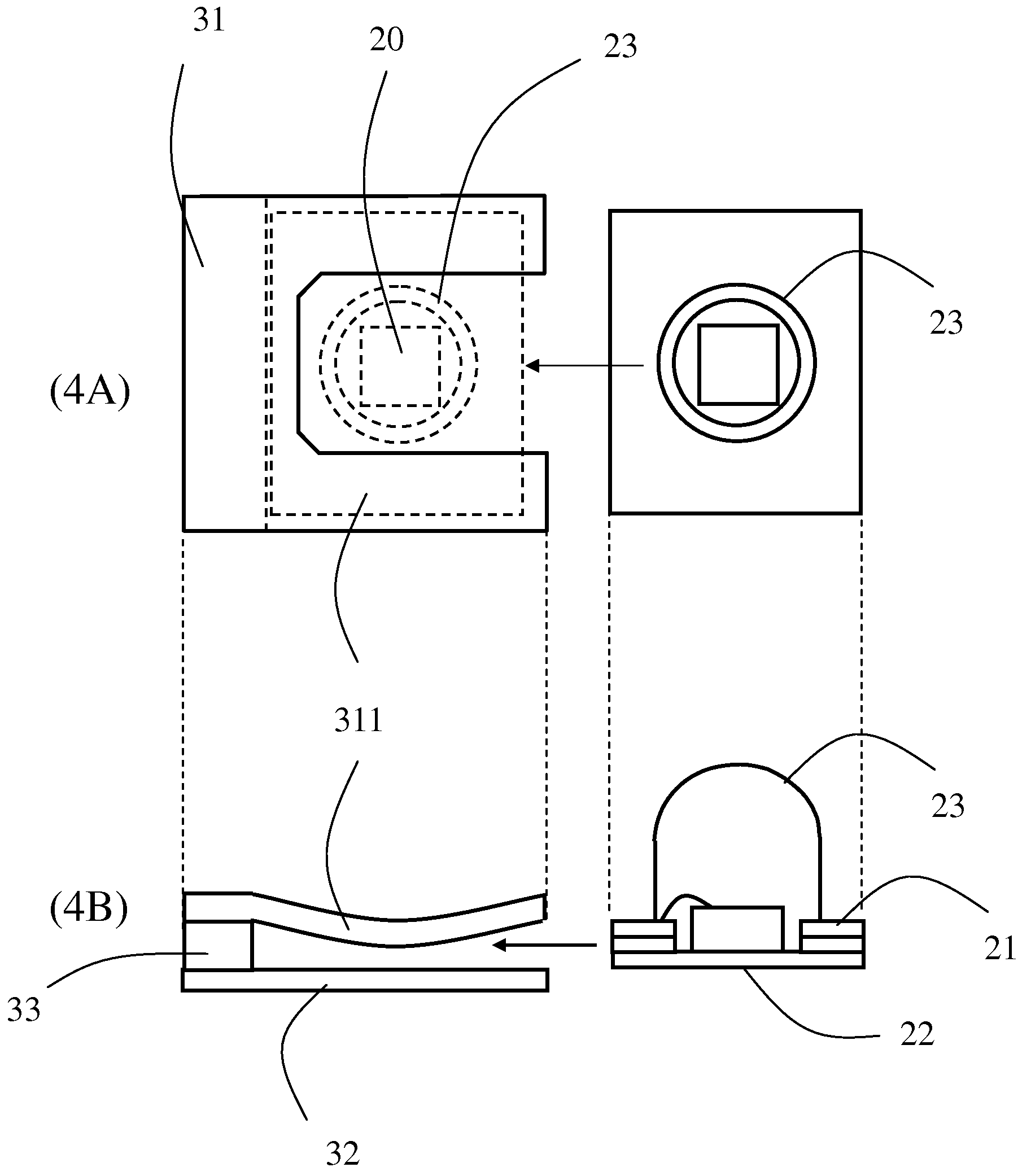
[0023]FIG. 3 is a top view of the present invention with a single light unit 50. A light board with a single cassette light unit 50 of the present invention is shown. A receptacle substrate of the light board has a first metal 31 and a second metal 32. The first metal 31 has a pair of elastic cantilevers 311 which hold the periphery of the top metal 21 of the pedestal of the cassette light unit 50 steadily, so as to anchor the cassette light unit 50 in position. Each elastic cantilever 311 is electrically coupled with the top metal 21 of the cassette light unit 50. The open area between the parallel elastic cantilevers 311 allows for light emission of the cassette light unit 50. An insulation material 33 is disposed between the first metal 31 and the second metal 32.

[0024]FIG. 4A is a top view of a light board of the present invention before insertion of a light unit 50. The first metal 31 has a parallel elastic cantilevers 311. A light unit 50 is inserted in between the first metal...

second embodiment

[0027]FIG. 6 is a top view of the present invention with matrix light unit slots. A matrix light board is illustrated as having, e.g., 4*3 receptacle slots, each slot is ready to receive a cassette light unit 50 (not shown in this figure).

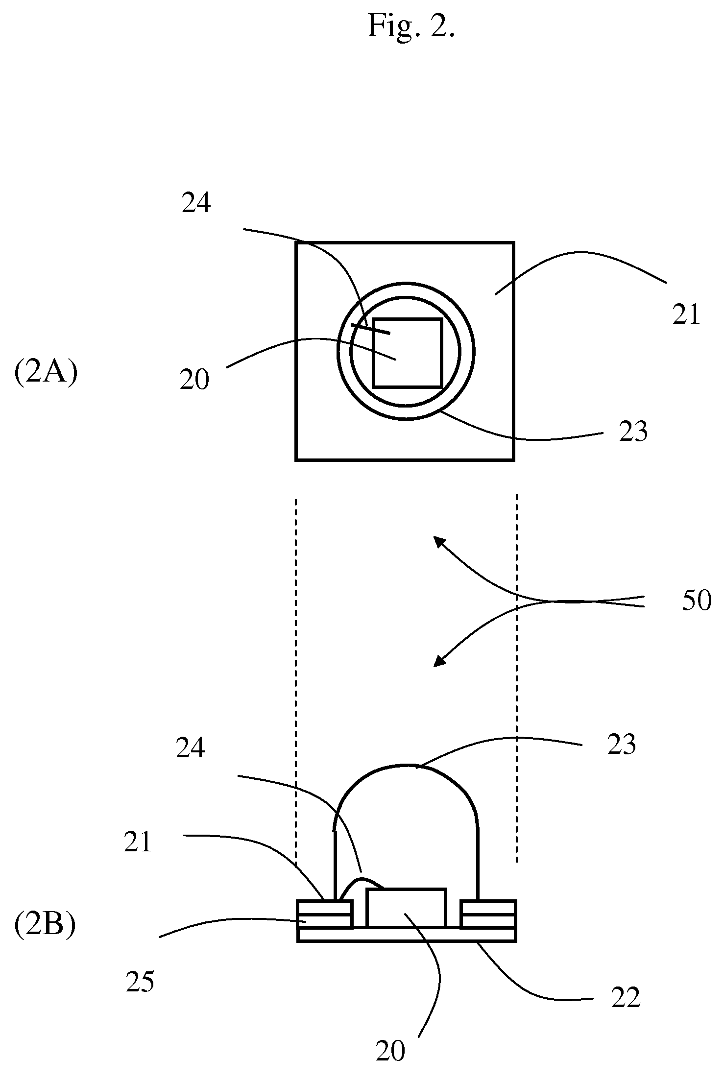
[0028]The transparent glue 23 can be in the shape of a lamp bulb, so as to modify the emitted light. The transparent bead 23 can be alternatively made into different products, such as, animals, plants, people, mountain or river sceneries, knives or forks and buildings etc. The product shall emit the light from the embedded light chip when the light unit is inserted into the receptacle in position, and become a lighting sculpture product.

[0029]FIG. 7 is a plane view of a matrix display according to the present invention.

[0030]A matrix display 99 made of 4*3 light units is shown as an example. Four coplanar parallel first metals (315˜318) are interweaved with three coplanar parallel second metals (325˜327); each of the first metals (315˜318) has thre...


PUM


Abstract

A light board is made with a receptacle substrate for accommodating cassette light units. The convenience of assembly and disassembly of the light units from the receptacle substrate makes the product easily to be maintained for changing different color light units, changing different displaying patterns, removing or replacing a failure light unit.

Description

RELATED APPLICATIONS[0001]The present application is based on, and claims priority from, Taiwan Application Serial Number 095105301, filed Feb. 17, 2006, the disclosure of which is hereby incorporated by reference herein in its entirety.BACKGROUND OF THE INVENTION[0002]1. Field of the Invention[0003]This invention relates to a matrix display of light emitted diodes.[0004]2. Description of the Related Art[0005]FIG. 1 is a prior art that illustrates a traditional light board. Conventional light board is made up with a printed circuit board (PCB) 10 on which a plurality of light-emitting diodes (LED) 11 are positioned. Only one LED 11 is shown in FIG. 1. Each of the diodes has bottom metals 11a and 11b. Corresponding metal circuits 10a and 10b is provided on the board 10 to electrically couple with the electrodes 11a and 11b of the light-emitting diode 11 respectively to form a traditional light-emitting diode display board. The shortcomings of the prior art are as follows: (1) inflexi...

Claims


Application Information

Patent Timeline
Patent Type & Authority Patents(United States)
IPC IPC(8): F21V21/00F21K99/00
CPCF21K9/00F21V19/042G09F9/33F21V19/001F21V19/004F21V19/0045F21V19/04
Inventor WU, JIAHN-CHANG
Owner CHENG KUNG CAPITAL LLC
Why Eureka
Try Eureka