
Board electrical connector, and electrical connector assembly having board electrical connector and middle electrical connector

Active Publication Date: 2008-11-04
HIROSE ELECTRIC GROUP
View PDF12 Cites 34 Cited by
  • Summary
  • Abstract
  • Description
  • Claims
  • Application Information

AI Technical Summary

Benefits of technology

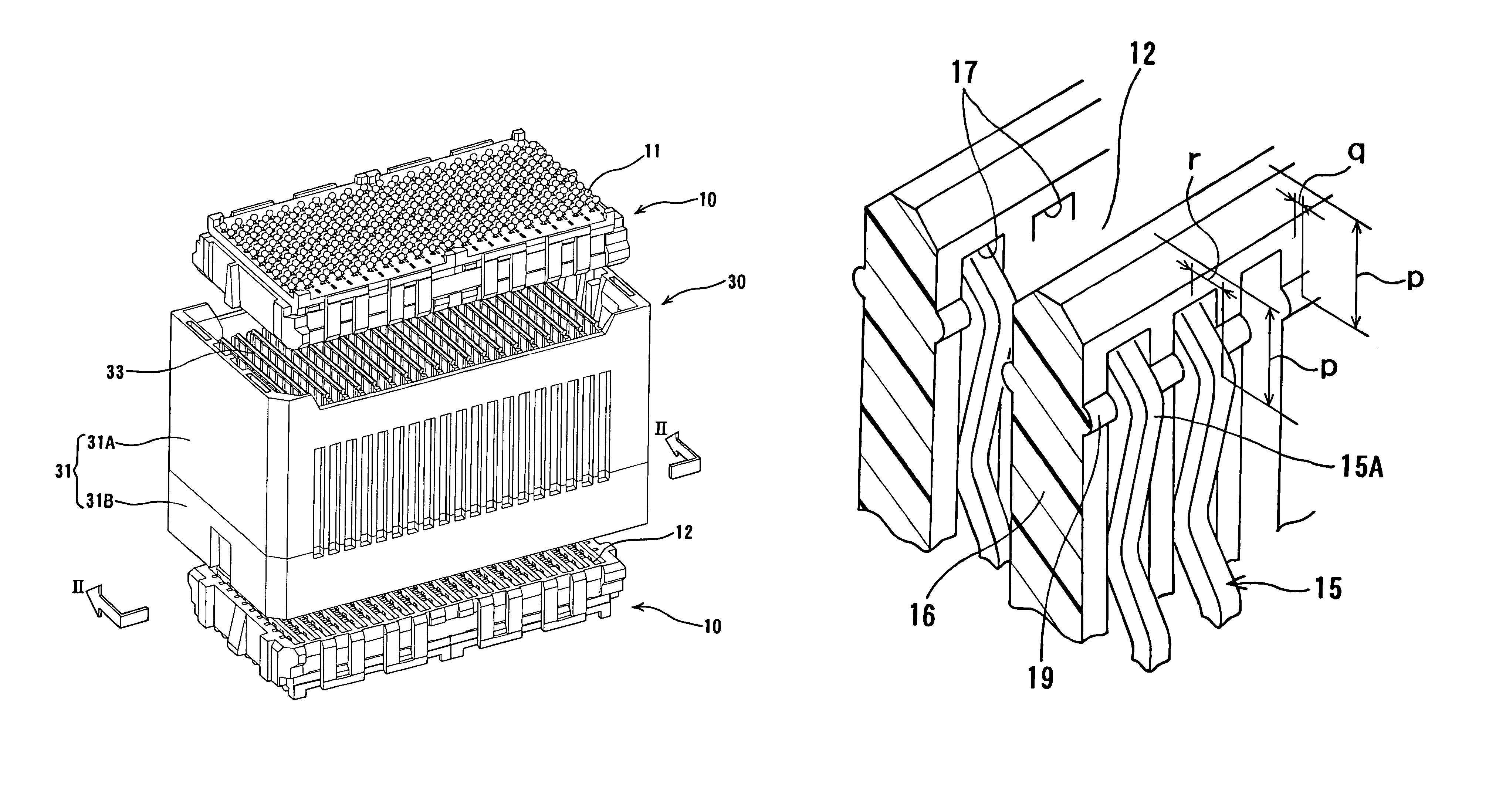
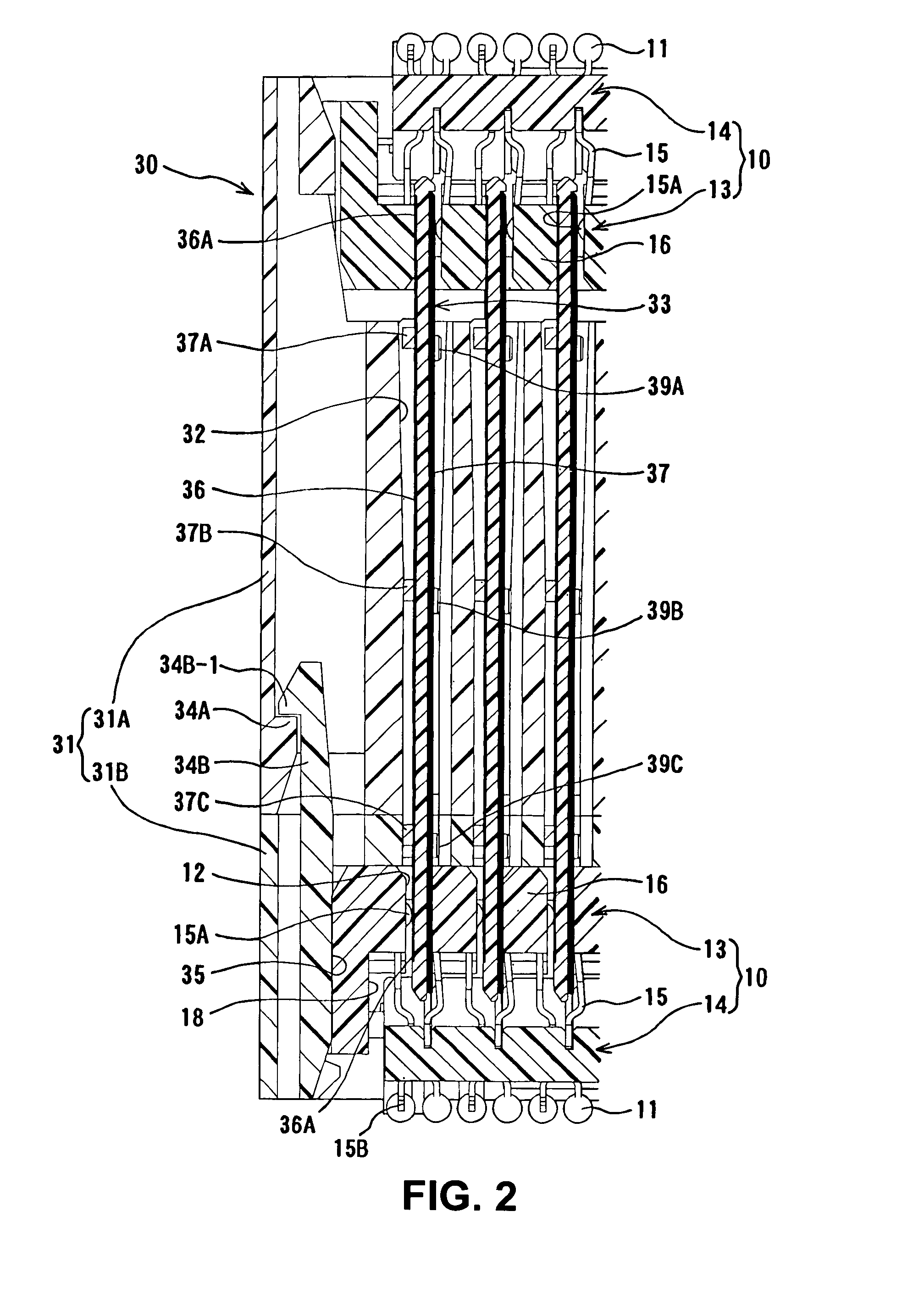
[0016]In the board electrical connector according to the present invention, the protrusion is provided. Accordingly, when there is the displacement upon fitting or when an external force is received after fitting, the protrusion prevents the middle member from being displaced. Further, in the position in which the displacement is prevented, the contact portion elastically contacts with the middle member. When the displacement is in the opposite direction, the contact portion follows the middle member to maintain an elastic contact within a pre-compression range until the contact portion is adjacent to the inner wall surface of the receiving groove on the other side in a direction in which the contact pressure of the terminal decreases.
[0018]According to the present invention, the contact portion and the protrusion do not have to be at exactly the same position in the receiving direction of the middle member. Alternatively, the contact portion and the protrusion may be substantially at the same position in which the contact portion and the protrusion overlap in the direction.
[0019]According to the present invention, the protrusion may be provided between the terminals adjacent to each other in a terminal arrangement direction. Accordingly, the protrusion is located between the terminals adjacent to each other. Thus, the contact pressure at the protrusion and the middle member is eased. Further, the protrusion contacts with the middle member evenly in the terminal arrangement direction, and the position of the middle member is to be stable. Further, the contact pressure between the pad portion and the terminal becomes stable.
[0021]Further, since the terminal can contact with the both surfaces of the middle member of the middle connector, the contact pressure of the terminal can be maintained regardless of the displacement upon fitting in the horizontal direction and a direction of external force in the horizontal direction after fitting. Thus, the contact becomes stable.
[0028]The shielding plate provided on the other surface effectively shields the circuit portion conducting with the pad portion provided on the other surface. The terminal of the board electrical connector that contacts with the shielding plate functions as the grounding terminal. In this case, a contact between the grounding terminal and the shielding plate can effectively deal with the displacement upon fitting of the connectors in the horizontal direction and an external force after fitting in the direction. Further, the contact is always elastic.
[0030]In addition, the protrusion provided on the inner wall surface of the receiving groove contacts with the middle member. Accordingly, further displacement of the middle member is regulated and the contact pressure of the contact portion is secured. The protrusion functions as a supporting point for the middle member, and the middle member may be sloped around the protrusion. Accordingly, the displacement of the middle connector and the connector on the board side upon fitting and a width to react to the external force after fitting may be further increased.

Problems solved by technology

However, when the connectors are fitted into each other to displace in one direction in a thickness direction of the middle member or when the connectors receive external force in the direction when or after the connectors are fitted into each other, the contact pressure of the terminal of the other surface may not be enough and the contact may become unstable or may be lost even though the terminal provided on one of the surfaces of the terminal of the middle member contacts with the middle member having enough contact pressure.
Further, in the terminal of the other surface, if a displacement of the thickness direction at the fitting of the connectors faces the other direction, the contact becomes unstable or may be lost.

Method used


Image

  • Board electrical connector, and electrical connector assembly having board electrical connector and middle electrical connector
  • Board electrical connector, and electrical connector assembly having board electrical connector and middle electrical connector
  • Board electrical connector, and electrical connector assembly having board electrical connector and middle electrical connector

Examples


Embodiment Construction

[0038]Hereunder, embodiments of the present invention will be explained with reference to the accompanying drawings.

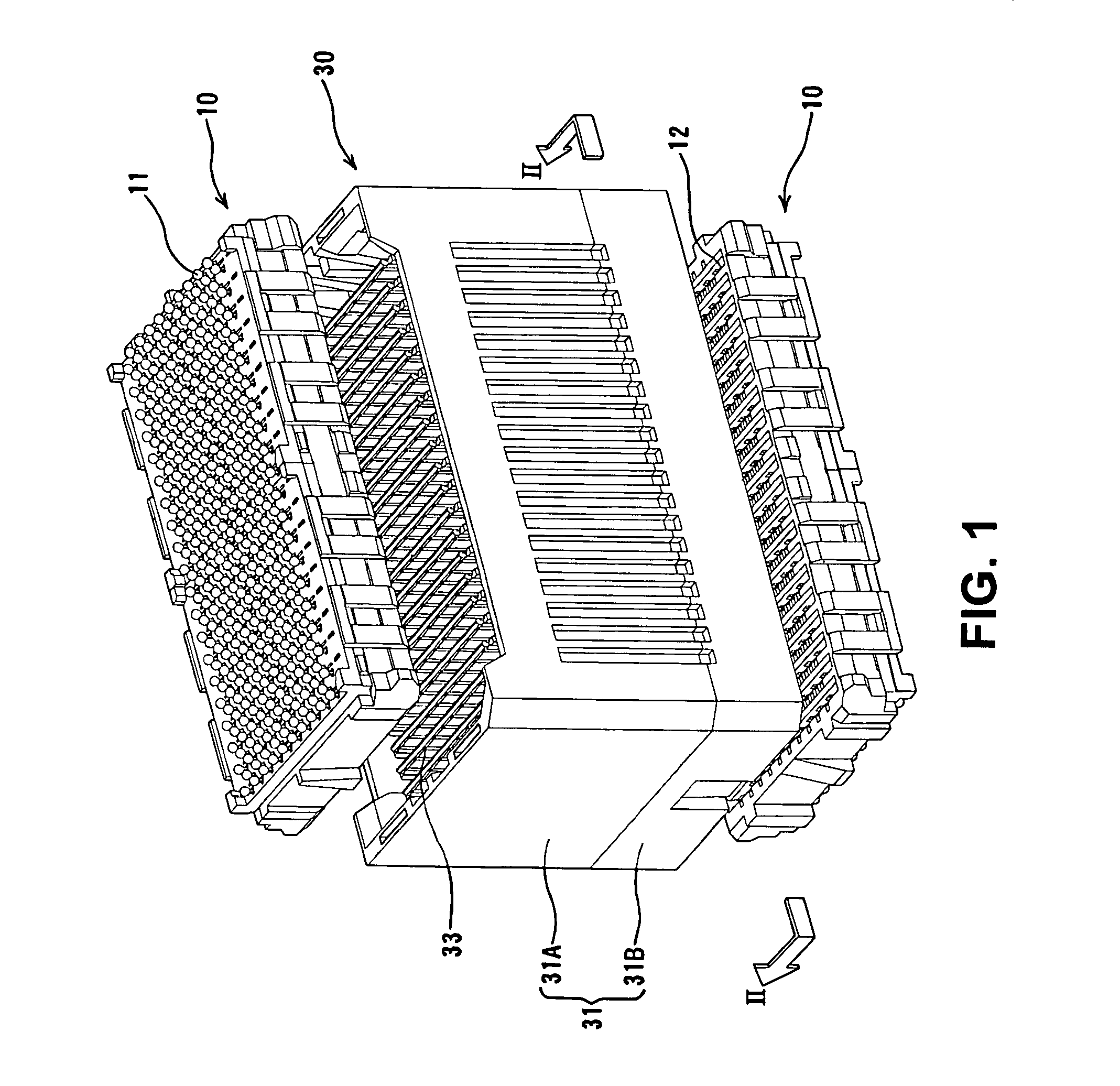
[0039]FIG. 1 is a perspective view of board electrical connectors 10 and a middle connector 30 before fitting according to an embodiment. In the embodiment shown in FIG. 1, the board connectors 10 having an identical configuration are situated symmetrically above and below the middle connector 30. A top surface of the top board electrical connector 10 and a bottom surface of the bottom board electrical connector 10 are provided with solder balls 11 in connection portions for terminals.

[0040]In the embodiment, the solder balls 11 connect the board connectors 10 with circuit boards (not shown). The board electrical connector 10 is provided with a plurality of receiving grooves 12 (refer to the bottom board electrical connector 10) on an opposite side of the side having the solder balls 11. A middle member 33 of the middle connector is inserted into the receiving groove 1...


PUM


Abstract

A board electrical connector includes a plurality of the terminals provided in a housing. The terminals are attached to a circuit board on one side of the housing and fit each other with a middle connector on the other side of the housing. The terminals contact with pad portions of middle members of the middle connector. A receiving groove having an opening portion to receive an edge portion of the middle member of the middle connector is provided in the housing. A contact portion of the terminal enters the receiving groove for contacting with the middle member with a contact pressure. A protrusion having a smaller entry amount than that of the contact portion is provided on an inner wall surface of the receiving groove in a receiving direction of the receiving groove. The protrusion is situated at the same position as that of the contact portion.

Description

BACKGROUND OF THE INVENTION AND RELATED ART STATEMENT[0001]The present invention relates to a board electrical connector attached to a circuit board, and an electrical connector assembly having the board electrical connector and a middle electrical connector.[0002]A conventional electrical connector assembly comprises a middle electrical connector (middle connector) and a board electrical connector (board connector). The electrical connector assembly of Patent Reference, for example, has been known. In the Patent Reference, the middle connector is provided with a plurality of middle members having a plate shape. The middle members are supported with a housing. Further, pads or connection portions are arranged along two edge portions of the middle members facing each other.[0003]When the middle connector fits into the board electrical connector, the contact portions of the terminals of the board connectors are connected to the pads.Patent Reference Japanese Patent Publication No. 200...

Claims


Application Information

Patent Timeline
IPC IPC(8): H01R12/00
CPCH01R13/514H01R12/7082H01R12/52
Inventor MATSUO, TSUTOMU
Owner HIROSE ELECTRIC GROUP
Learn More