Resetable over-current and/or over-temperature protection system

a protection system and over-current technology, applied in the direction of protective switch operation/release mechanism, protective switch details, relays, etc., can solve the problems of compact fluorescent lamps (cfl) flickering, limited current through the load to a very small value, and certain types of load to behave undesired

Active Publication Date: 2008-11-04
THE HONG KONG POLYTECHNIC UNIV
View PDF24 Cites 12 Cited by
  • Summary
  • Abstract
  • Description
  • Claims
  • Application Information

AI Technical Summary

Problems solved by technology

Furthermore, the resistance of the heated PTC element 107 is very large, and therefore the current through the load is limited to a very small value.
However, disadvantages exist with such conventional design in that the small current through the load 103, even in the over-current or over-temperature situation, may cause certain types of load to behave undesirably.
For example, such small current may cause a compact fluorescent lamp (CFL) to flicker.

Method used


Image

  • Resetable over-current and/or over-temperature protection system
  • Resetable over-current and/or over-temperature protection system
  • Resetable over-current and/or over-temperature protection system

Examples


Embodiment Construction

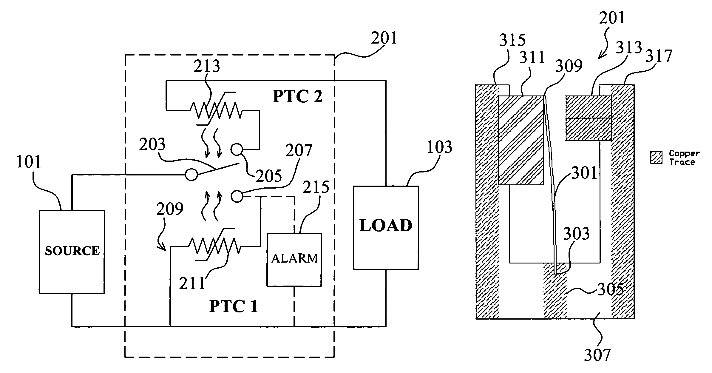
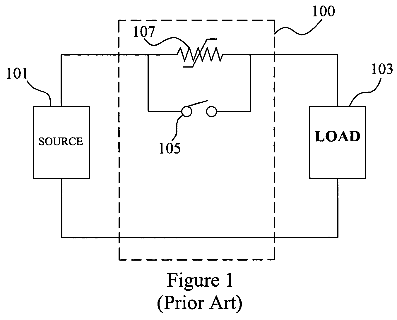
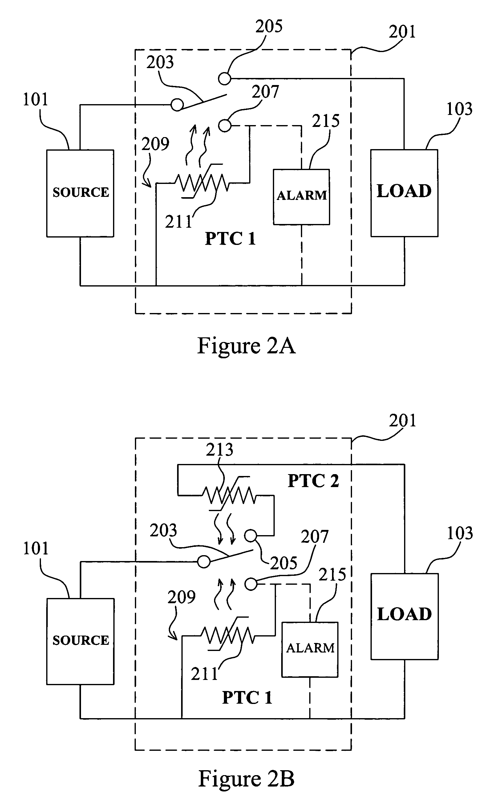
[0032]FIG. 2A illustrates an electrical protection system 201 according to an exemplary embodiment of the present invention. Similar to the conventional design of FIG. 1, the system 201 is electrically connected between the power supply 101 and the load 103. The system 201 firstly has a bimetal switch 203 switchable between two electrical contacts 205, 207. In a normal state, the switch 203 is switched to the contact 205. In this state, in the exemplary embodiment, the power supply 101, the switch 203 and the load 103 are connected in series such that an operating current passes through the switch 203 and the load 103. The system 201 further has an alternate path 209 including a first PTC element 211 between the electrical contact 207 and the power supply 101. When the current through or the temperature of the bimetal switch 203 is over its respective rated value, the bimetal switch 203 switches to the electrical contact 207 automatically to operate in a fault state such that the sw...


PUM


Abstract

An electrical protection system, which can be connected between an electrical power supply and an electrical load, firstly includes a switch switchable between a normal state in which the switch is electrically connected in series between the power supply and the load such that an operating current passes through the switch and the load, and a fault sate in which the switch is disconnected with the load such that no current passes through the load. The switch switches to the fault state in an over-current or an over-temperature situation. The system further includes a controller operable in an open state when the switch operates in the normal state, in which state the controller is electrically disconnected from the power supply such that no current passes through the controller, or a closed state when the switch operates in the fault state, in which state the controller is electrically connected in series between the switch and the power supply such that a self-holding current passes through the switch and the controller. The controller operates to automatically set the switch to the normal state when the self-holding current is off.

Description

BACKGROUND[0001]1. Field of the Invention[0002]This invention relates to electrical circuit over-current and / or over-temperature protection.[0003]2. Background of the Invention[0004]Positive temperature coefficient (PTC) devices are widely used in electrical circuit over-current or over-temperature protections. Such examples include U.S. Pat. No. 6,421,216, filed on Apr. 7, 2000, assigned to EWD, LLC and entitled “Resetable Overcurrent Protection Arrangement,” and U.S. Pat. No. 6,577,223, filed on Oct. 10, 2001, assigned to Uchiya Thermostat Co., Ltd. and entitled “Thermal Protector.” Both are herein incorporated by reference.[0005]A conventional PTC circuit protection system 100 is shown in FIG. 1, connected between an electrical power supply 101 and an electrical load 103. The system 100 generally includes a bimetal switch 105 and a PTC element 107 thermally coupled and electrically connected in parallel. In a normal situation, the bimetal switch 105 is closed, and the operating c...

Claims


Application Information

Patent Timeline
Patent Type & Authority Patents(United States)
IPC IPC(8): H01H37/52H01H37/14H01H37/16
CPCH01H1/504H01H37/08H01H71/04H01H71/16H01H71/164
Inventor LEE, YIM-SHULI, JIANQINGCHOW, MARTIN HOI-LAMSIU, KAM-WAH
Owner THE HONG KONG POLYTECHNIC UNIV
Why Eureka
Try Eureka