Loop antenna unit and radio communication medium processor

a radio communication medium and processor technology, applied in the field of loop antenna units and radio communication medium processors, can solve the problems of increasing weight, affecting other electronic devices, and affecting the influence of unnecessary noise from a peripheral part, so as to achieve stable reading and writing characteristics, easy expansion of communication range, and suppression of the resonance frequency of the first loop antenna

Inactive Publication Date: 2008-11-04
PANASONIC CORP
View PDF25 Cites 37 Cited by
  • Summary
  • Abstract
  • Description
  • Claims
  • Application Information

AI Technical Summary

Benefits of technology

[0038]According to the structure of the present invention, while the non-electric current fed loop antenna is installed adjacently to the loop antenna unit, when the electric current is fed only to the first loop antenna, the first loop antenna can be electro-magnetically coupled to the non-electric current fed loop antenna by a mutual induction by making the second loop antenna function as a buffer. Accordingly, even if a plurality of non-electric current fed loop antennas are increased, the variation of the resonance frequency of the first loop antenna can be suppressed. As a result, a matching of impedance of the loop antenna unit may not need to be adjusted.
[0039]Further, according to the structure of the present invention, in an accommodating shelf and a display shelf for carrying out a goods management and a book management, while the influence of a structure made of wood, a resin or metal forming the accommodating shelf in a place where the antenna is attached is greatly reduced and stable reading and writing characteristics are satisfied, a communication range can be easily enlarged. Thus, the radio communication medium processor excellent in its convenience and extensibility can be provided.
[0040]Especially, since the loop antenna unit is a grounded type loop antenna unit having the metal member in the loop antenna, under a state that the metal member exists, that is, under the state of an unbalanced loop antenna in which one end of the two opening ends of the loop antenna is electrically grounded in the metal member, the impedance of the antenna is previously adjusted. Accordingly, the reference potential (ground potential) of the antenna is stabilized and the variation of the antenna impedance can be minimized. Therefore, the influence to antenna characteristics by the peripheral structure is eliminated irrespective of the quality of a material such as wood, a resin or metal forming the accommodating shelf in the place where the loop antenna unit is installed and an adjustment may not be required during installing the loop antenna unit.
[0041]The electric current fed loop antenna unit and the non-electric current fed loop antenna unit using the grounded type loop antenna are prepared, so that the adjacent loop antennas are electro-magnetically coupled to each other by a mutual induction. The number of the non-electric current fed loop antenna units is merely increased and arranged closely together so that a communication range can be easily enlarged. It is to be understood that the non-electric current fed unit also eliminates the influence to the antenna characteristics by the peripheral structure and an adjustment is not necessary during installing the loop antenna unit.
[0042]Further, since the non-electric current fed loop antenna unit is connected to the matched load via the resonance circuit and the matching circuit of the loop antenna, the generation of a standing wave due to a reflected wave and the generation of a mismatching loss can be suppressed and the density of a re-radiated magnetic flux is more increased. Accordingly, the efficiency of all the loop antenna unit is very high and stable characteristics can be obtained and a total communication range can be greatly extended.
[0043]Further, since an electric current is not fed to the non-electric current fed loop antenna unit, the non-electric current fed loop antenna does not cause an excessively consumed electric power and gives no influence to other electronic device, so that an electric power can be saved. Further, the electric current fed loop antenna unit and the non-electric current fed loop antenna unit are laminated and a laminated structure is stored in a case, so that a thinned and miniaturized device can be realized and the device can be easily carried and installed. Further, durability and a weather resistance is improved, so that the device can be installed by simply placing it. Especially, when a communication range is desired to be changed, such a structure is particularly effective to increase the communication range to an optimum level.

Problems solved by technology

Thus, a problem arises that the influence of unnecessary noise from a peripheral part is liable to be received and the increase of the radiation of an electric field to a remote place greatly affects other electronic devices.
Further, problems arise in view of an electric performance and a mechanical performance that the antenna itself is liable to be affected by structures such as neighboring metal owing to the increase of the antenna size, and the improvement of strength is required in terms of a mechanism, and as a result, a weight is increased.

Method used


Image

  • Loop antenna unit and radio communication medium processor
  • Loop antenna unit and radio communication medium processor
  • Loop antenna unit and radio communication medium processor

Examples


first embodiment

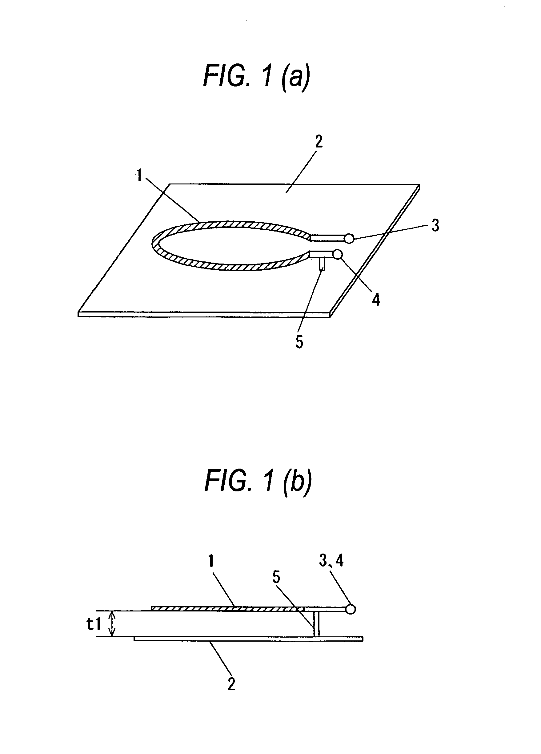
[0086]FIG. 1(a) is a perspective view of a first loop antenna unit in a first embodiment of the present invention and FIG. 1(b) is a sectional view of the first loop antenna unit in the first embodiment of the present invention.

[0087]In FIGS. 1(a) and 1(b), 1 designates a loop antenna and 2 designates a metal member. 3 designates one end of opening end parts of the loop antenna 1 and 4 designates the other end of the opening end parts of the loop antenna 1. 5 designates an electric conductive wire rod, a plate material or a bar material to electrically ground a part near the opening end part of the loop antenna 1 in the metal member. Further, the loop antenna 1 is arranged in substantially parallel with the metal member 2 with a desired space t1 between them. The loop antenna 1 may be configured in a loop shape having an opening part in a center. The form thereof may be circular, substantially rectangular or polygonal. Further, a material of the loop antenna I may be suitably select...

second embodiment

[0108]FIG. 11 is a perspective view showing a using example of a radio communication medium processor in a second embodiment of the present invention.

[0109]FIG. 12 is a perspective view showing a second using example of the radio communication medium processor in the second embodiment of the present invention.

[0110]FIG. 11 shows the first using example. In the drawing, on a goods shelf 17 made of wood, a resin or metal, goods or books 18 to which IC tags 19 are attached are placed. Between the goods shelf 17 and the goods or the books 18, electric current fed loop antenna units 15 and non-electric current fed loop antenna units 16 are arranged in a relation of 1 to N (N≦1). In an example of an arrangement, on an upper shelf in the drawing, the electric current fed loop antenna unit 15 is arranged in the vicinity of a central part, and on a lower shelf in the drawing, the electric current fed loop antenna unit 15 is arranged in a side. In such a way, since the radio communication med...

third embodiment

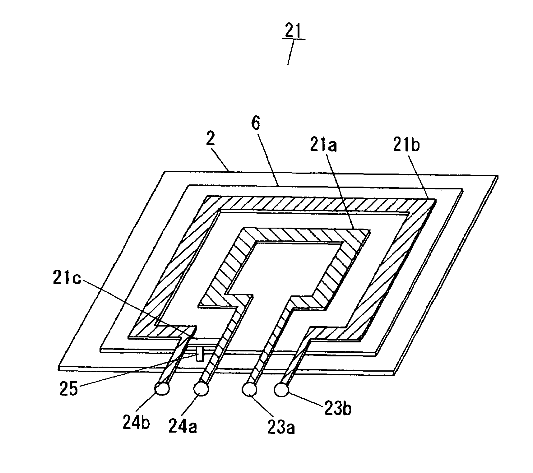
[0112]FIG. 13(a) is a perspective view of a loop antenna unit in a third embodiment of the present invention and FIG. 13(b) is a side view of the loop antenna unit in the third embodiment of the present invention.

[0113]A loop antenna unit 21 has an inner loop antenna 21a (a first loop antenna) and an outer loop antenna 21b (a second loop antenna) as shown in FIG. 13(a). The outer loop antenna 21b surrounds the outer periphery of the inner loop antenna 21a. The inner loop antenna 21a and the outer loop antenna 21b are arranged on the same plane as shown in FIG. 13(a). However, when the outer loop antenna 21b is arranged so as to surround the inner loop antenna 21a, the outer loop antenna 21b and the inner loop antenna 21a are not necessarily arranged on the same plane. As described below, when an electric current is fed only to the inner loop antenna 21a, if the inner loop antenna 21a is magnetically connected to the outer loop antenna 21b, they may be arranged on different planes.

[0...


PUM


Abstract

It is an object of the present invention to provide a radio communication medium processor having a stable performance that does not receive a limitation for an installed place, especially, the influence of a metallic structure, does not need to adjust the resonance frequency of an antenna or an impedance, is excellent in its convenience and extensibility upon installation and strong for unnecessary noise from a periphery.In electric current fed loop antenna units, non-electric current fed loop antenna are arranged in doughnut shapes outside the substantially same planes of electric current fed loop antennas so as to surround the electric current fed loop antennas. Thus, when non-electric current fed loop antenna units are installed linearly, in radial directions and in arrays adjacently to electric current fed loop antenna units, the influence of the non-electric current fed loop antenna units to the antenna characteristics of the electric current fed loop antenna units can be suppressed. When the non-electric current fed loop antenna units are extended and increased, the antennas of the electric current fed loop antenna units do not need to be adjusted.

Description

TECHNICAL FIELD[0001]The present invention relates to a radio communication medium processor for supplying electric power and transmit data to a radio communication medium such as a non-contact IC card or an IC tag stuck to goods or books to be accommodated in a goods shelf to obtain receive data from the radio communication medium by the variation of a load. More particularly, the present invention relates to a loop antenna unit and a radio communication medium processor preferably used for an accommodating shelf or a display shelf in which the management of books and the management of goods can be automatically realized.BACKGROUND ART[0002]Usually, a reader writer system using the IC card is ordinarily referred to as a non-contact IC card system, and has been put to practical use in a physical distribution system, a transportation system, a goods management and book management system or the like using a frequency band of, for instance, 13.56 MHz. This system includes the IC card h...

Claims


Application Information

Patent Timeline
Patent Type & Authority Patents(United States)
IPC IPC(8): H01Q21/00H01Q11/12
CPCG06K19/07749G06K19/07771H01Q1/2216H01Q1/2225H01Q7/00H01Q19/10H01Q21/06H01Q21/08H01Q1/48H01Q1/52
Inventor MARUYAMA, KEISUKEDEGUCHI, FUTOSHI
Owner PANASONIC CORP
Why Eureka
Try Eureka