
Loop antenna unit and radio communication medium processor
- Summary
- Abstract
- Description
- Claims
- Application Information
AI Technical Summary
Benefits of technology
Problems solved by technology
Method used
Image

Examples
first embodiment
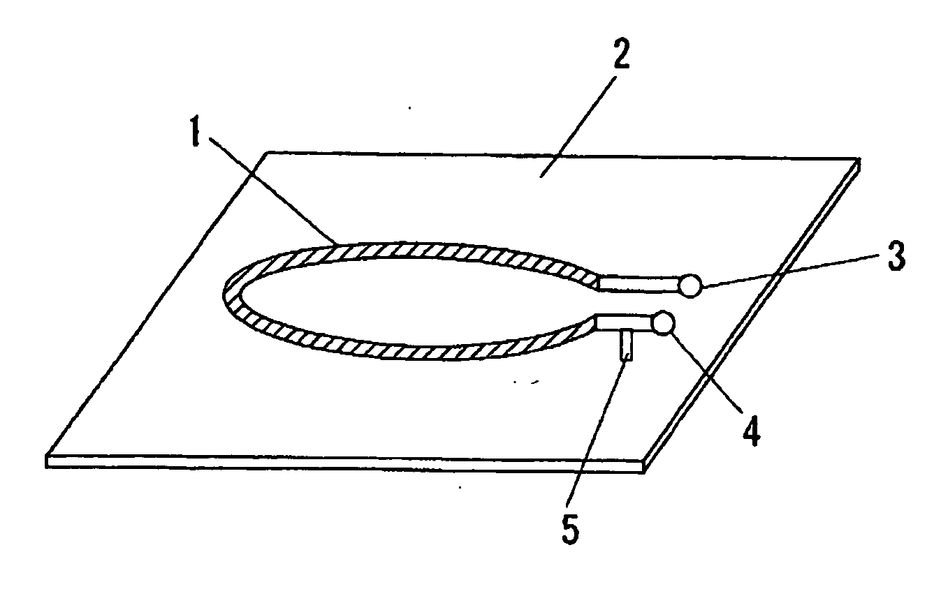
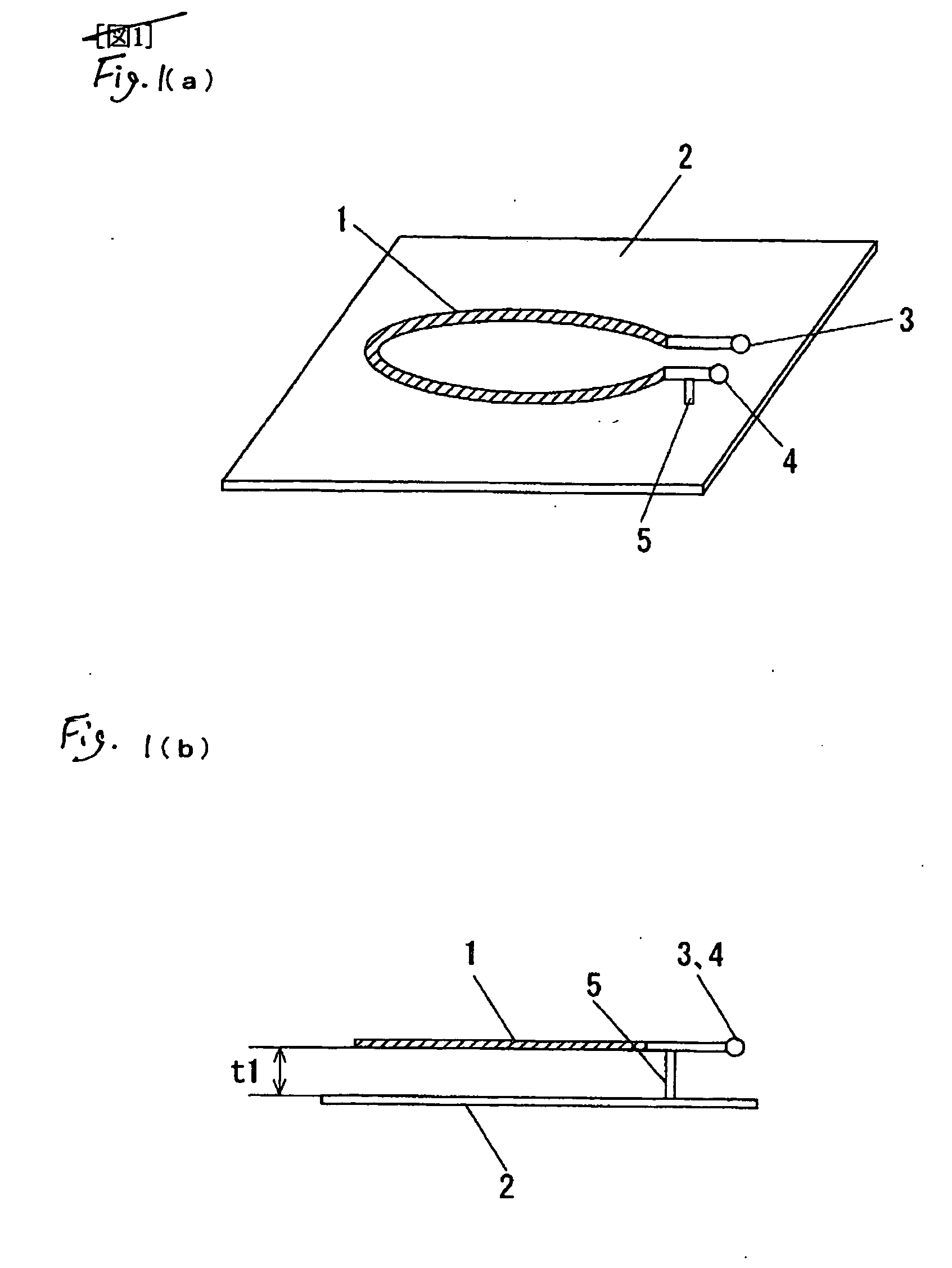
[0086]FIG. 1(a) is a perspective view of a first loop antenna unit in a first embodiment of the present invention and FIG. 1(b) is a sectional view of the first loop antenna unit in the first embodiment of the present invention.
[0087] In FIGS. 1(a) and 1(b), 1 designates a loop antenna and 2 designates a metal member. 3 designates one end of opening end parts of the loop antenna 1 and 4 designates the other end of the opening end parts of the loop antenna 1. 5 designates an electric conductive wire rod, a plate material or a bar material to electrically ground a part near the opening end part of the loop antenna 1 in the metal member. Further, the loop antenna 1 is arranged in substantially parallel with the metal member 2 with a desired space t1 between them. The loop antenna 1 may be configured in a loop shape having an opening part in a center. The form thereof may be circular, substantially rectangular or polygonal. Further, a material of the loop antenna I may be suitably sele...
second embodiment
[0108]FIG. 11 is a perspective view showing a using example of a radio communication medium processor in a second embodiment of the present invention.
[0109]FIG. 12 is a perspective view showing a second using example of the radio communication medium processor in the second embodiment of the present invention.
[0110]FIG. 11 shows the first using example. In the drawing, on a goods shelf 17 made of wood, a resin or metal, goods or books 18 to which IC tags 19 are attached are placed. Between the goods shelf 17 and the goods or the books 18, electric current fed loop antenna units 15 and non-electric current fed loop antenna units 16 are arranged in a relation of 1 to N (N≦1). In an example of an arrangement, on an upper shelf in the drawing, the electric current fed loop antenna unit 15 is arranged in the vicinity of a central part, and on a lower shelf in the drawing, the electric current fed loop antenna unit 15 is arranged in a side. In such a way, since the radio communication m...
third embodiment
[0112]FIG. 13(a) is a perspective view of a loop antenna unit in a third embodiment of the present invention and FIG. 13(b) is a side view of the loop antenna unit in the third embodiment of the present invention.
[0113] A loop antenna unit 21 has an inner loop antenna 21a (a first loop antenna) and an outer loop antenna 21b (a second loop antenna) as shown in FIG. 13(a). The outer loop antenna 21b surrounds the outer periphery of the inner loop antenna 21a. The inner loop antenna 21a and the outer loop antenna 21b are arranged on the same plane as shown in FIG. 13(a). However, when the outer loop antenna 21b is arranged so as to surround the inner loop antenna 21a, the outer loop antenna 21b and the inner loop antenna 21a are not necessarily arranged on the same plane. As described below, when an electric current is fed only to the inner loop antenna 21a, if the inner loop antenna 21a is magnetically connected to the outer loop antenna 21b, they may be arranged on different planes....
PUM
 Abstract
Description
Claims
Application Information