
Transflective switchable double-cell LCD device

a dual-cell, liquid crystal display technology, applied in optics, non-linear optics, instruments, etc., can solve the problems of unfavorable transflective liquid crystal display devices, lower transmittance ratio, and lower reflectivity, and achieve optimal performance

Inactive Publication Date: 2008-11-04
INNOLUX CORP
View PDF7 Cites 5 Cited by
  • Summary
  • Abstract
  • Description
  • Claims
  • Application Information

AI Technical Summary

Benefits of technology

The present invention is a transflective liquid crystal display device that can achieve a well-lighted display in both the transmissive mode and the reflective mode using the same pixels. This is achieved by disposing an optical element that can switch between transmission of light from a light source and reflection of external light by applying a voltage. The use of a polymer type liquid crystal display element as the optical element eliminates the need for a polarizer and allows for optimal performance in both modes. The device also includes switching control means for controlling the power supply to switch between the transmissive mode and the reflective mode. The optical element can have a color filter and can be a polymer dispersed type liquid crystal display element or a polymer network type liquid crystal display element. The technical effect of this invention is to provide a display device that can achieve a well-lighted display in both modes using the same pixels.

Problems solved by technology

However, in the above-mentioned transflective liquid crystal display devices, since a single pixel has a transmissive region and a reflective region, there are disadvantages that the transmittance ratio is lower than that in the transmissive type liquid crystal display device, while the reflectivity is lower than that in the reflective type liquid crystal display device.
In other words, in terms of luminosity, transflective liquid crystal display devices are unfavorable as compared with transmissive type liquid crystal display devices and reflective type liquid crystal display devices.

Method used


Image

  • Transflective switchable double-cell LCD device
  • Transflective switchable double-cell LCD device
  • Transflective switchable double-cell LCD device

Examples


embodiment 1

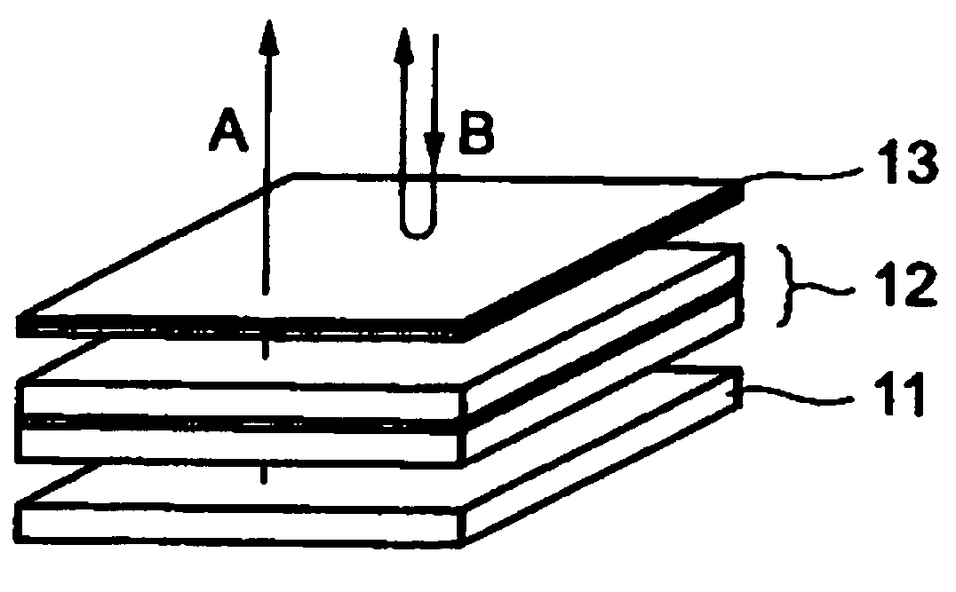
[0031]This embodiment describes an arrangement where an optical element, which is capable of switching between transmission of light from the light source and reflection of external light by applying the voltage, is arranged over the liquid crystal panel. FIG. 1 is a view showing an arrangement of the transflective liquid crystal display device of the present invention.

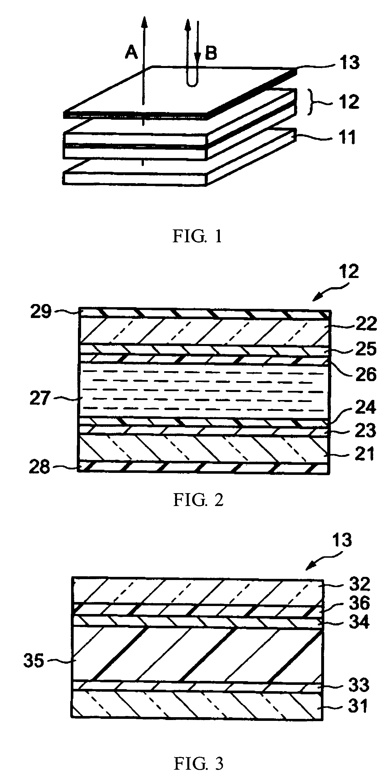
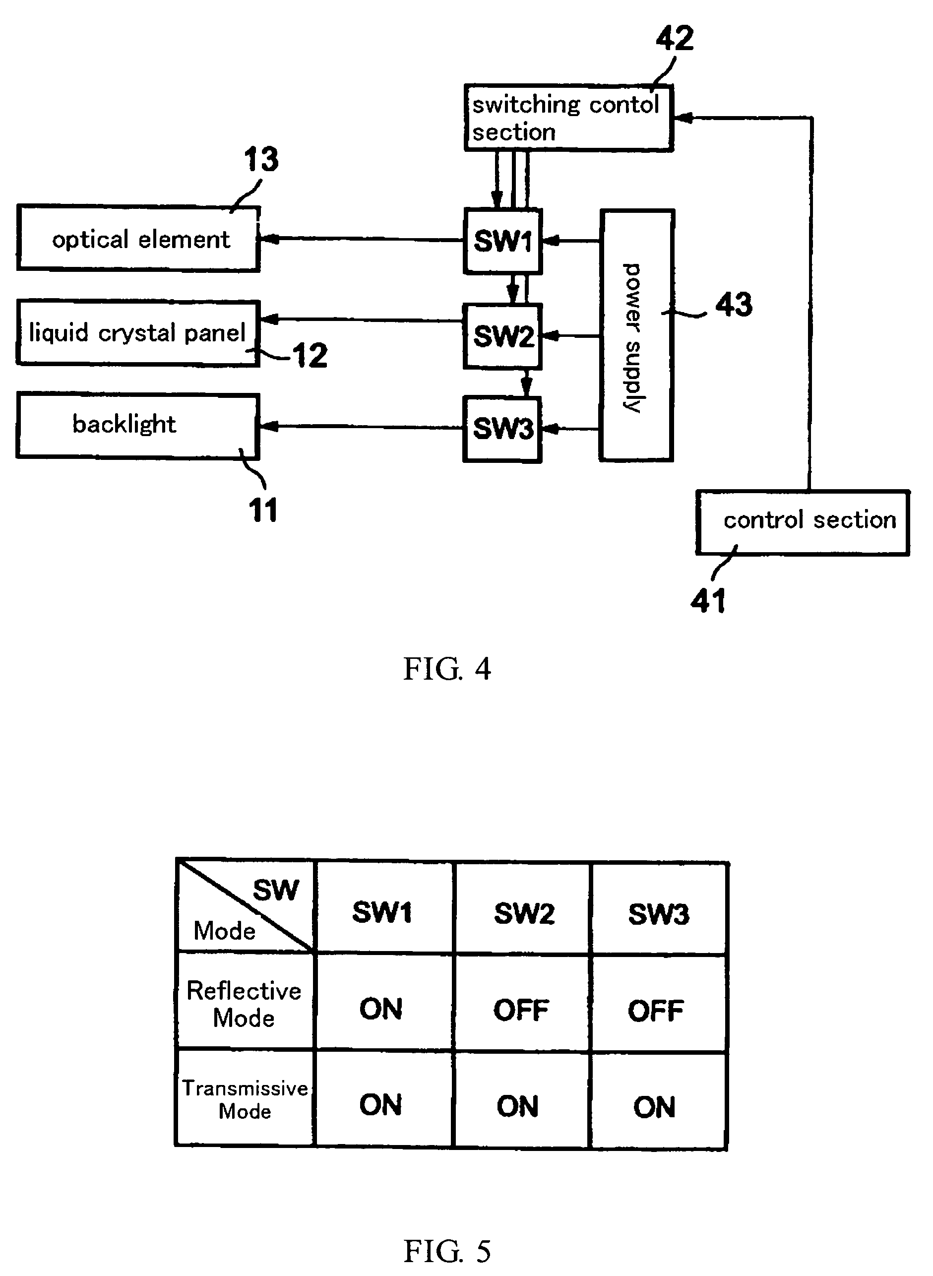
[0032]The transflective liquid crystal display device as shown in FIG. 1 principally has a backlight 11 that is the light source used in the transmissive mode, a liquid crystal panel 12, arranged over the backlight 11, for operating as a display element in the transmissive mode, and an optical element 13, arranged over the liquid crystal panel 12, for operating as a display element in the reflective mode.

[0033]As the backlight 11, there may be backlights used in general liquid crystal display devices.

[0034]Liquid crystal panels used in monochrome transmissive type LCD, for example, TN (Twisted Nematic) liquid crystal...

embodiment 2

[0053]This embodiment describes an arrangement where an optical element, which is capable of switching between transmission of light from the light source and reflection of external light by applying the voltage, is arranged between the light source and the liquid crystal panel. FIG. 6 is a view showing an arrangement of the transflective liquid crystal display device of the present invention.

[0054]The transflective liquid crystal display device as shown in FIG. 6 principally has a backlight 61 that is the light source used in the transmissive mode, an optical element 62, arranged over the backlight 61, for switching transmission of the light from the backlight 61 and reflection of the external light by applying the voltage, and a liquid crystal panel 63, arranged over the optical element 62, for operating as a display element in the transmissive mode.

[0055]As the backlight 61, there may be backlights used in general liquid crystal display devices.

[0056]Liquid crystal panels used i...


PUM

PropertyMeasurementUnit
shapeaaaaaaaaaa
transmittanceaaaaaaaaaa
reflectivityaaaaaaaaaa

Abstract

To be realized the well-lighted display by using the whole pixels in the reflective mode and the transmissive mode. In a reflective mode, an optical element 13 is used as liquid crystal display element. That is, the optical element 13 operates as liquid crystal display element by applying the voltage. In this case, the optical element 13 reflects the external light since the optical element 13 is a scattering state with regard to non-applying pixel (arrow B). In a transmissive mode, a liquid crystal panel 12 is used as liquid crystal display element. That is, the liquid crystal panel 12 operates as liquid crystal display element by applying the voltage. In this case, the optical element 13 passes light from a backlight 11 since the optical element 13 is a transmissive state (arrow A). And the optical element 13 plays a color filter part and does not operates as display element.

Description

BACKGROUND OF THE INVENTION[0001]1. Field of the Invention[0002]The present invention relates to the transflective liquid crystal display device, particularly to the transflective liquid crystal display device usable the whole pixels in the reflective mode and the transmissive mode.[0003]2. Description of Related Art[0004]So-called transflective liquid crystal display devices have been put into full-scale practical use in which external light incident from a front side is reflected to lead to the front side, while incident light from a rear side due to the backlight system is transmitted to lead to the same front side. The liquid crystal display devices of this type provide effective image display by the external light (ambient light) principally (reflective mode) under well-lighted environments, and by the emitted light in the backlight system principally (transmissive mode) under low light environments.[0005]Such a type of liquid crystal display device is disclosed in a document o...

Claims


Application Information

Patent Timeline
Patent Type & Authority Patents(United States)
IPC IPC(8): G02F1/1335G02F1/1333G02F1/1334G02F1/13357G02F1/1347
CPCG02F1/13476G02F1/1334G02F2203/09G02F2001/133626G02F1/133626G02F1/1335G02F1/133
Inventor UKAWA, YUSEI
Owner INNOLUX CORP
Features
  • Generate Ideas
  • Intellectual Property
  • Life Sciences
  • Materials
  • Tech Scout
  • Unparalleled Data Quality
  • Higher Quality Content
  • 60% Fewer Hallucinations
Learn More