Board supporting mechanism, board supporting method, and component mounting apparatus and component mounting method using the same mechanism and method

a technology of supporting mechanism and supporting method, which is applied in the direction of electrical apparatus construction details, electrical apparatus casing/cabinet/drawer, coupling device connection, etc., can solve the problem of difficulty in properly selecting a material having a suitable elastic for

Inactive Publication Date: 2008-11-04
PANASONIC CORP
View PDF22 Cites 10 Cited by
  • Summary
  • Abstract
  • Description
  • Claims
  • Application Information

AI Technical Summary

Benefits of technology

[0021]In order to solve the aforementioned issues in the conventional art, an object of the present invention is to provide: a board supporting mechanism and a board supporting method, a component mounting apparatus and a viscous material applying apparatus utilizing the board supporting mechanism and a component mounting method and a viscous material applying method utilizing the board supporting method; a support pin; and a pin-erecting guide plate, capable of making adjustment for the support height of a support pin unnecessary upon changing a position of a support pin in accordance with a change in model of a circuit board to carry out a setup for model changes in the circuit board in a considerably efficient manner.
[0026]When the support pin and the pin erecting guide plate are changed together with new ones in accordance with a change in model of the circuit board, the support pin may be held in the pin-erecting through-hole of the pin-erecting guide plate while being prevented from slip-off.
[0033]The elastic plate members having the connecting portions are connected to each other so that it is possible to obtain a pin-erecting guide plate having a desired area.
[0046]With this configuration, even when the support pin and the pin erecting guide plate are changed together with a new one in accordance with a change in model of the circuit board, a reference of a support height of the support pin corresponds with the surface of the support table. Therefore, it is unnecessary to adjust the parallelism between the plate and the support table. That is, it is unnecessary to adjust the support height of the support pin. Accordingly, it is possible to make a setup for a change in model of the circuit board in a considerably more efficient manner in comparison with the conventional art. As one example of a more specific configuration, the support table is formed to have an even plane (surface) without irregularities and to have high rigidity.
[0050]The support pin according to the present invention has a longitudinal length equal to a distance between the surface of the support table at an upper dead center of the raising / lowering type support table and the bottom face of the circuit board held by the board holding device, is held in the direction substantially perpendicular to the surface of the support table, and has one end in the longitudinal direction brought into contact with the bottom face of the circuit board and the other end in the longitudinal direction brought into contact with the surface of the support table, thereby supporting the circuit board. Accordingly, a reference of a support height of the support pin does not correspond with the surface of the plate but corresponds with the surface of the support table. Thus, it is unnecessary to adjust the support height of the support pin. Accordingly, it is possible to make a setup for a change in model of the circuit board in a considerably more efficient manner in comparison with the conventional art.

Problems solved by technology

In contrast, one of the disadvantages of this method is that the pin supporting plate 130 with a number of support pins 128 being attached thereto needs to be taken out of the component mounting apparatus 101, and thereafter, the pin supporting plate 130 with the support pins 128 needs to be again attached to the component mounting apparatus 101 upon mounting a component.
Moreover, in the system of Patent Document 2 which prepares the support pin 128 itself as an elastic body, depending on the amount of protrusion of the mounted component 110, the deformation of the component 110 and influences to adjacent components due to the elastic force of the support pin 128 tend to be caused, with the result that it is sometimes difficult to properly select a material having a suitable elastic force as the support pin 128.

Method used


Image

  • Board supporting mechanism, board supporting method, and component mounting apparatus and component mounting method using the same mechanism and method
  • Board supporting mechanism, board supporting method, and component mounting apparatus and component mounting method using the same mechanism and method
  • Board supporting mechanism, board supporting method, and component mounting apparatus and component mounting method using the same mechanism and method

Examples


first embodiment

[0072]Referring to the drawings, the following description will discuss a board supporting mechanism and a board supporting method according to the present invention.

[0073]Herein, a component mounting apparatus and a component mounting method as examples of a processing apparatus and a processing method capable of using the board supporting mechanism and the board supporting method are described later.

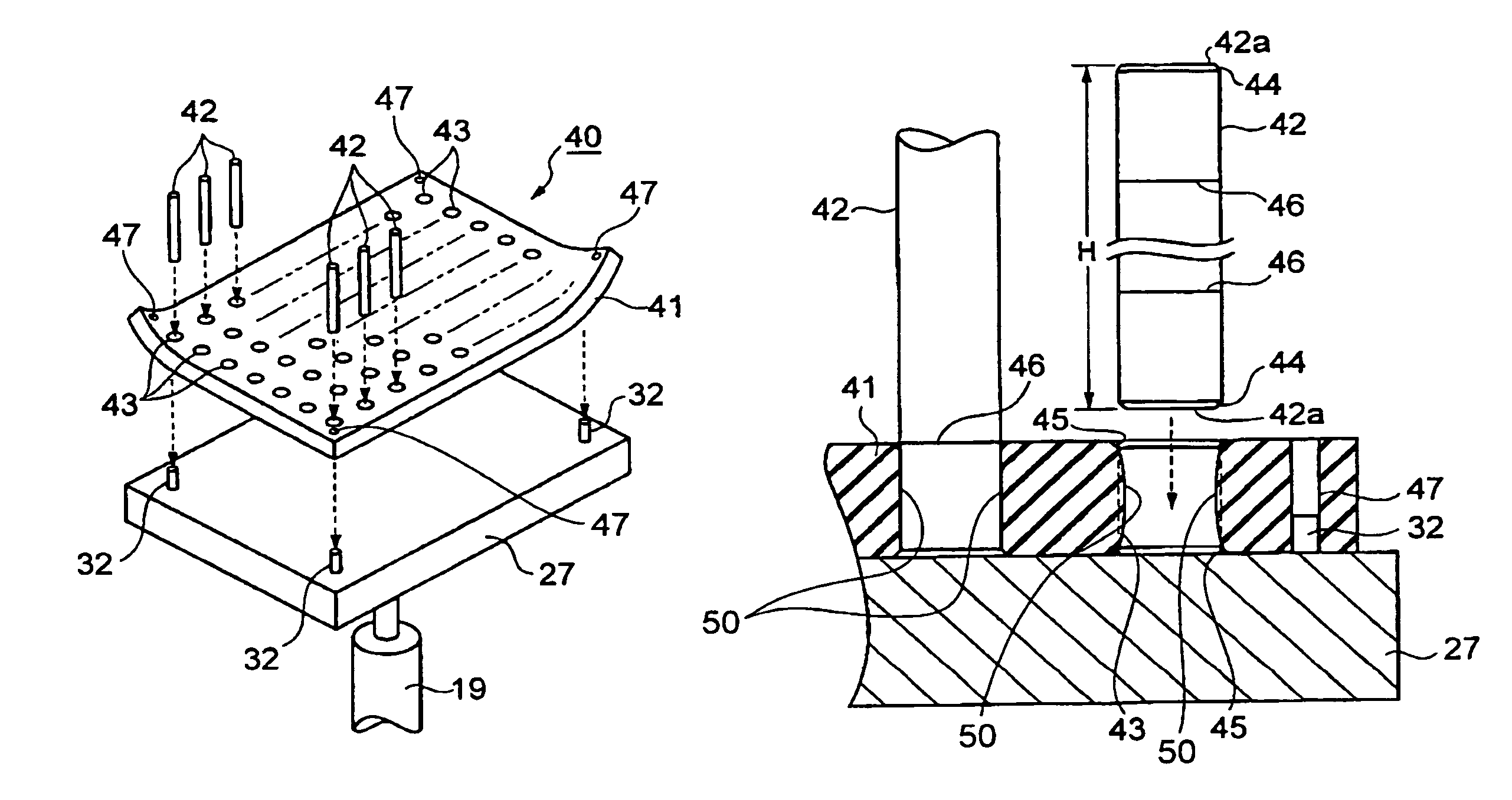
[0074]FIG. 1 illustrates a board supporting mechanism 40 according to the first embodiment. In FIG. 1, the board supporting mechanism 40 is constituted by a rectangular-shaped support table 27 that can be raised / lowered between a board supporting position and a board-support releasing position, a rectangular-shaped pin-erecting guide plate (hereinafter, referred to as a guide plate) 41 to be secured onto the support table 27 as indicated by broken line arrows, and support pins 42 to be attached to the guide plate 41 as indicated by broken line arrows in the same manner. The support tab...

second embodiment

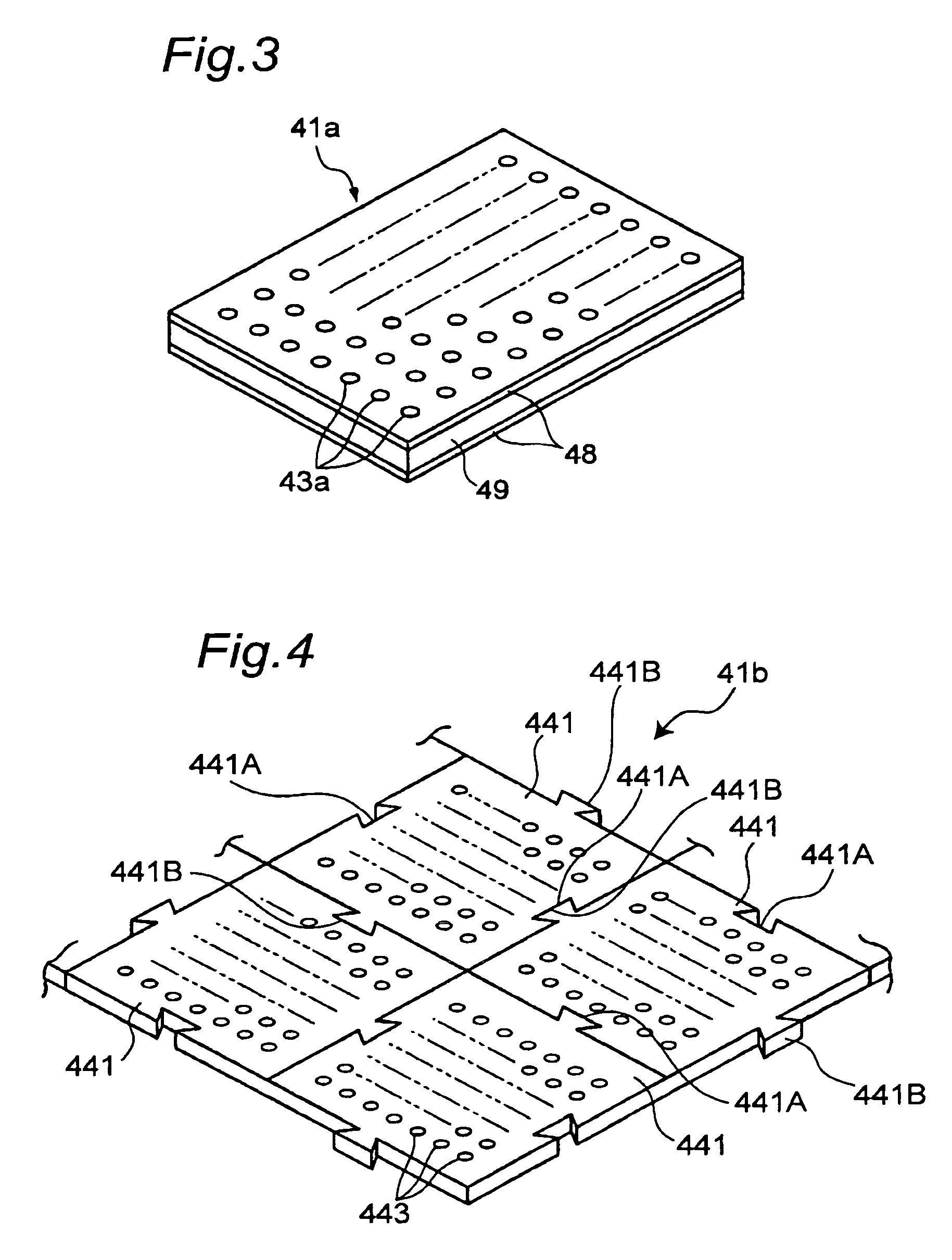
[0127]In FIG. 5, the guide plate 51 to be used in the second embodiment is formed by a plastic material with a box shape with one side being open, and is constituted by a peripheral portion 52 having a plate shape surrounding the periphery with a fixed height (thickness), a plane portion 53 forming a surface facing the circuit board 14 and a plurality of tube-shaped holder portions 54 capable of holding the support pins 42. In FIG. 5, only one portion of the holder portions 54 is illustrated, with the other portion being omitted.

[0128]The respective thicknesses of the peripheral portion 52 made of a plastic material; the plane portion 53 and the holder portions 54 are designed so as to ensure the respectively required strengths. The height (thickness) “g” of the peripheral portion 52 is preferably designed to have a sufficient height for holding the support pins 42 in the direction substantially perpendicular, and the height “g” of the peripheral portion 52 may be set to about 10 mm...

third embodiment

[0138]FIG. 8, which illustrates another mode corresponds to FIG. 7B and is a cross-sectional side view that illustrates a state in which the paired half plates 62 are superposed one on the other with the holder portions 64 of the paired half plates 62 thereby being positioned face to face with each other. Herein, in place of the elastic body plate 63 to be sandwiched between the half plates 62, a holder ring 66 made of an elastic body as one example of an elastic member is placed in each of the holder portions 64.

[0139]In FIG. 8, step portions 67 are formed on the tips of the respective holders 64 on the sides facing each other, and each of the holder rings 66 is fitted to each of the grooves formed by the two step portions 67. When the pair of half plates 62 are fastened to each other by using a fastening member such as a bolt, or combined with each other through bonding or the like, each holder ring 66 is secured in the groove formed by the two step portions 67 inside the holder ...


PUM

PropertyMeasurementUnit
thicknessaaaaaaaaaa
outer diameteraaaaaaaaaa

Abstract

A board supporting mechanism and a board supporting method eliminating an adjustment of a support height of a support pin upon position-changing of the support pin in accordance with a change in the model of a circuit board, as well as a component mounting apparatus and a component mounting method. A single or a plurality of support pin(s) (42) have one end(s) and are brought into contact with a bottom face of a circuit board (14) to support the bottom face of the circuit board (14) and the other end(s) are brought into contact with a surface of a support table (27) for raising / lowering the support pin(s) (42). Each support pin is held in a direction substantially perpendicular to the surface of the support table (27). The one end(s) of the support pin (42), held in the direction substantially perpendicular to the surface of the support table (27), is brought into contact with the bottom face of the circuit board (14), and thereby, the support pins support the circuit board (14).

Description

BACKGROUND OF THE INVENTION[0001]The present invention relates to: a board supporting mechanism; a board supporting method; a component mounting apparatus utilizing the board supporting mechanism, and a component mounting method utilizing the board supporting method to mount a component on a circuit board; a viscous material applying apparatus and a viscous material applying method for applying a viscous material such as cream solder, adhesive, or silver paste onto a circuit board; a support pin; and a pin-erecting guide plate. More specifically, the present invention relates to: a board supporting mechanism and a board supporting method capable of supporting a circuit board from a bottom side thereof upon mounting a component or upon applying a viscous material; a component mounting apparatus and a viscous material applying apparatus respectively utilizing the board supporting mechanism and a component mounting method and a viscous material applying method respectively utilizing th...

Claims


Application Information

Patent Timeline
Patent Type & Authority Patents(United States)
IPC IPC(8): H05K7/14
CPCH05K7/142H05K13/0069Y10T29/53174Y10T29/49126Y10T29/49153Y10T29/4913Y10T29/53265
Inventor IKEYA, KEISHIKIDO, KAZUOHACHIMURA, TETSUTAROUCHIDA, HIDEKI
Owner PANASONIC CORP
Why Eureka
Try Eureka