Rotation state detecting device and rotation state detecting method

a detection device and rotating state technology, applied in hurricane shutters, door/window protective devices, instruments, etc., can solve the problems of wrong ignition timing of cylinders, inability to detect the rotation direction of toothed wheels,

Active Publication Date: 2007-04-17
MITSUBISHI ELECTRIC CORP
View PDF17 Cites 1 Cited by
  • Summary
  • Abstract
  • Description
  • Claims
  • Application Information

AI Technical Summary

Benefits of technology

[0011]With a rotation state detecting device and a rotation state detecting method according to the invention it is possible to detect the direction of rotation of a rotating body, and adjustment for device dispersion and offset and the like is almost unnecessary.

Problems solved by technology

In a rotation detecting device of the kind shown in JP-A-2000-337922, a speed of rotation is detected by taking the difference between the outputs of two magneto-resistance effect element patterns, and there has been the problem that even if the toothed wheel rotates backward, the output waveform is the same (FIG. 2 of JP-A-2000-337922), and consequently the rotation direction of the toothed wheel cannot be detected.
With rotation detecting devices of related art, because the rotation direction cannot be detected, even if this kind of backward rotation occurs, the problem may arise that this is detected as forward rotation and consequently the ignition timing of the cylinders is wrong the next time the engine is started.
And in a reverse rotation detecting device according to JP-A-2001-108700, ‘Rotating Body Reverse Rotation Detecting Device and Reverse Rotation Detecting Method’, it is necessary to set two threshold levels from outside, and there has been the problem that due to dispersion among devices and mounting accuracy issues it has been necessary to adjust each device individually.

Method used


Image

  • Rotation state detecting device and rotation state detecting method
  • Rotation state detecting device and rotation state detecting method
  • Rotation state detecting device and rotation state detecting method

Examples


first preferred embodiment

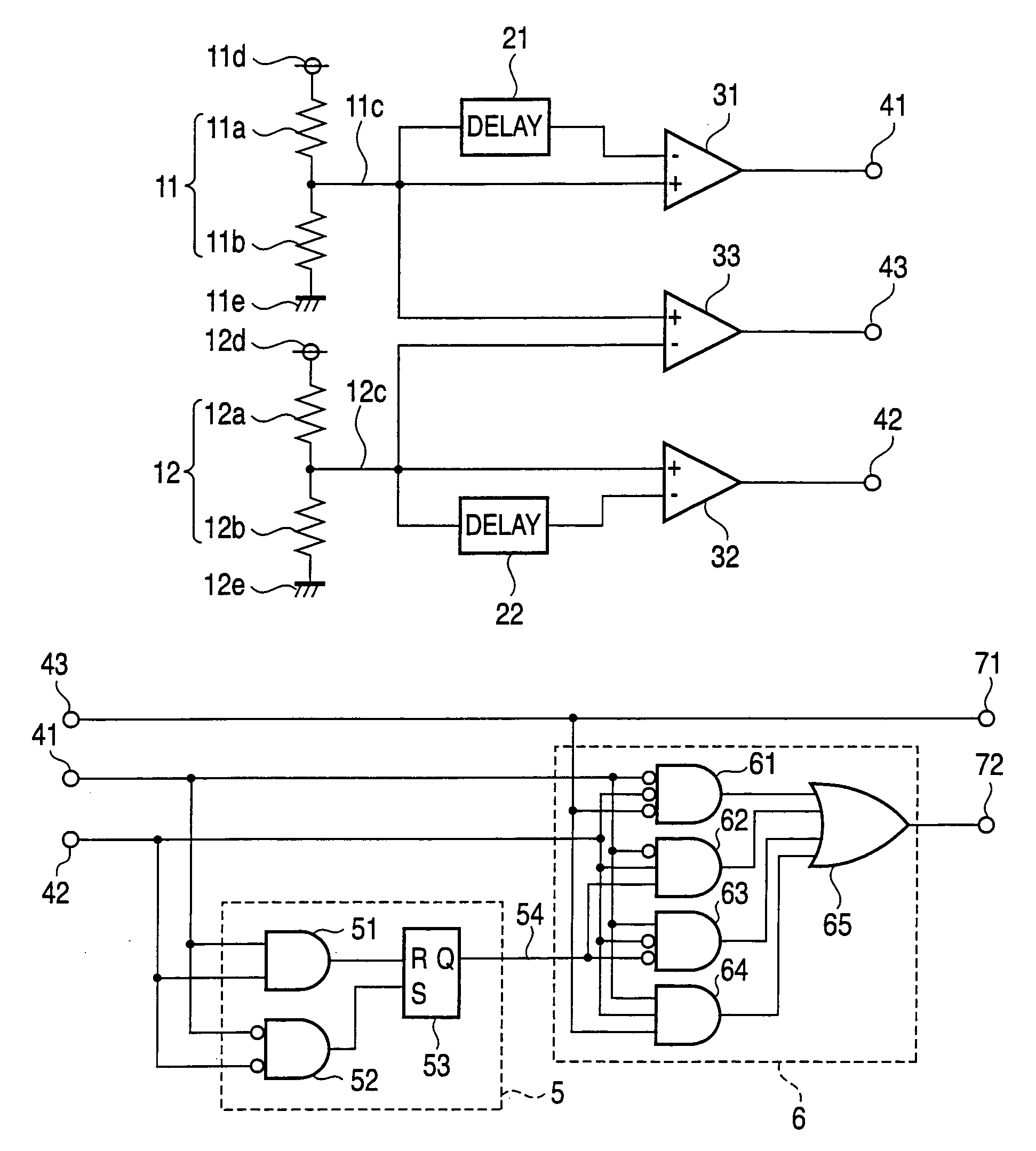
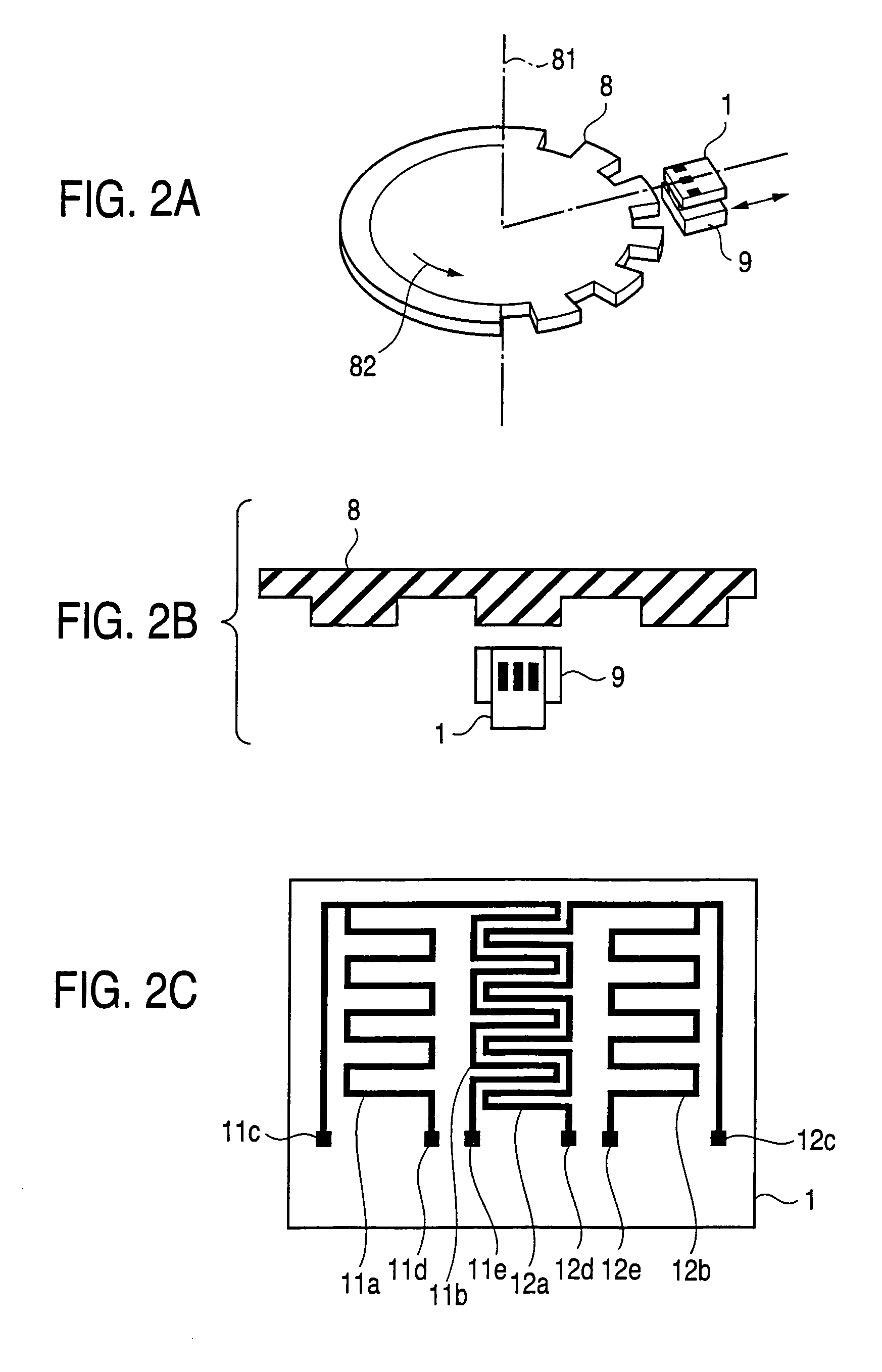
[0023]FIGS. 1A and 1B are block diagrams showing main parts of a first preferred embodiment of a rotation state detecting device according to the invention. FIGS. 2A to 2C are views illustrating the construction of a magnetic circuit used in the rotation state detecting device of the first preferred embodiment, FIG. 2A being a perspective view, 2B a plan view and 2C a view of a pattern of magneto-resistance effect elements. In FIGS. 2A to 2C, a magneto-resistance effect element unit 1 is made up of magneto-resistance effect elements 11a, 11b, 12a and 12b. Referring to FIG. 1, the magneto-resistance effect elements 11a, 11b are connected and form a first bridge circuit 11 having a grounded terminal 11e, a terminal lid to which a constant voltage is applied, and a terminal 11c that outputs a center point voltage. Similarly, the magneto-resistance effect elements 12a, 12b are connected and form a second bridge circuit 12 having a grounded terminal 12e, a terminal 12d to which a constan...

second preferred embodiment

[0043]FIG. 9 is a block diagram showing a main part of a rotation state detecting device according to a second preferred embodiment. Comparators 31, 32 compare center point voltages 11c, 12c with the outputs of delay circuits 21, 22, but to prevent misoperation, respective low pass filters 23, 24 are inserted to remove a noise component from the signals being compared. In FIG. 9, a high-frequency noise component of the center point voltage 11c, 12c outputs is removed with low pass filters 23, 24, and the outputs of the low pass filters 23, 24 are compared with the outputs of delay circuits 21, 22 for delaying those outputs by the comparators 31, 32. Similarly, the outputs of the low pass filters 23, 24 are compared with each other by a comparator 33. As a result, because signals in which noise caused by external disturbances is removed from them are compared, misoperation caused by noise can be suppressed.

[0044]Although in this second preferred embodiment the outputs of the low pass...

third preferred embodiment

[0045]FIG. 10 is a block diagram showing a main part of a rotation state detecting device according to a third preferred embodiment. Whereas in the first preferred embodiment the increasing / decreasing directions of the center point voltages 11c, 12c were detected using delay circuits 21, 22 and comparators 31, 32, alternatively the analog values of the center point voltages 11c, 12c may be converted into digital values with A / D-convertors 25, 26, and these digital values (signals) may be delayed using flip-flop circuits 27, 28 to detect the increasing / decreasing direction. In FIG. 10, the A / D-convertors 25, 26 convert the analog values (signals) of the center point voltages 11c, 12c into digital values (signals). The flip-flop circuits 27, 28 delay the center point voltages 11c, 12c converted to digital values by 1 clock period.

[0046]Logic circuits 34, 35 compare the digital values of the center point voltages 11c, 12c (the outputs of the A / D-convertors 25, 26) with the digital valu...


PUM


Abstract

A rotation state detecting device capable of detecting the direction of rotation of a rotating body includes first and second bridge circuits made up of magneto-resistance effect elements, a first comparator for detecting the increasing / decreasing direction of the center point voltage of the first bridge circuit, a second comparator for detecting the increasing / decreasing direction of the center point voltage of the second bridge circuit, a third comparator for detecting the difference between the center point voltage of the first bridge circuit and the center point voltage of the second bridge circuit, and logic value information deriving means for outputting “1” when the logic values of the outputs of the first comparator and the second comparator are both “1”, outputting “0” when they are both “0”, and continuing to output the previous value at other times, the direction of rotation of the rotating body being determined on the basis of a combination of the outputs of the first, second and third comparators and the logic value information deriving means.

Description

BACKGROUND OF THE INVENTION[0001]1. Field of the Invention[0002]This invention relates to a rotation state detecting device and a rotation state detecting method for detecting the rotation state of a pronged magnetic rotating body.[0003]2. Description of the Related Art[0004]Generally, for example in an engine of an automotive vehicle, to detect the speed of the engine and the ignition timing of multiple cylinders, a revolution sensor is provided. In a revolution sensor, for example as shown in JP-A-2000-337922, ‘Rotation Detecting Device’, a magnet for directing a bias field at the teeth of a rotating toothed wheel and two magneto-resistance effect element patterns whose resistance values change along with changes in the bias field are provided, the two magneto-resistance effect element patterns are disposed symmetrically about the magnetic center axis of the bias magnet, and changes in the magnetic field caused by rotation of the toothed wheel are outputted as voltages. By the dif...

Claims


Application Information

Patent Timeline
Patent Type & Authority Patents(United States)
IPC IPC(8): G01P3/44G01B7/30G08B21/00G01P3/488G01B7/14G01D5/12G01D5/14G01D5/16G01D5/244G01D5/245G01P13/04G01R33/06
CPCG01D5/145G01D5/2451G01D2205/85E05Y2800/422E06B9/00E06B2009/005
Inventor TSUKAMOTO, MANABUMURAKAMI, TAKAAKIARIYOSHI, YUJIOHNAKADO, TAKAHIROKOSASAYAMA, YASUHIRO
Owner MITSUBISHI ELECTRIC CORP
Why Eureka
Try Eureka