Quick release buckle

a quick-release buckle and buckle technology, applied in the direction of fastenings, garment fasteners, press-button fasteners, etc., can solve the problems of unintended parting of the buckle components, the design of the interlocking buckle does not provide a convenient way of parting the interlocking buckle components, and the release levers of the female components are prone to being overstressed and broken

Active Publication Date: 2008-11-11
ILLINOIS TOOL WORKS INC
View PDF12 Cites 23 Cited by
  • Summary
  • Abstract
  • Description
  • Claims
  • Application Information

AI Technical Summary

Benefits of technology

[0007]The male component includes a tongue projecting forwardly from a base. The tongue is configured and dimensioned for insertion into the receiving channel of the female component via its access opening, and a shoulder on the tongue coacts in snap engagement with the catch on the release lever to retain the two components in an interlocked relationship. The lift tab overlies and is spaced above the base of the male component to thereby provide a means of prying or otherwise upwardly deflecting the release lever to disengage its catch from the tongue shoulder and thereby accommodate separation of the buckle components.
[0009]Preferably, the lift tab is angled upwardly to prevent the lanyard cord from obstructing the access opening of the female component's receiving channel.
[0010]Preferably, the base of the male component is configured with a notch into which the lanyard cord may be releaseably tucked and thus safeguarded from inadvertent snagging.
[0011]In accordance with still another aspect of the present invention, the side walls of the female component have stops that overlap and limit the extent to which the release lever can be upwardly deflected, thus safeguarding the release lever from being excessively stressed and broken.

Problems solved by technology

For example, their design does not provide a convenient way of parting the interlocked buckle components without using the lanyard.
The release levers of the female components are prone to being overstressed and broken by excessive pulling forces on the lanyards.
Lanyards are limited to thin webs that are generally sewn into place, and the lanyards are susceptible to inadvertent snagging, resulting in unintended parting of the buckle components.

Method used


Image

  • Quick release buckle
  • Quick release buckle
  • Quick release buckle

Examples


Embodiment Construction

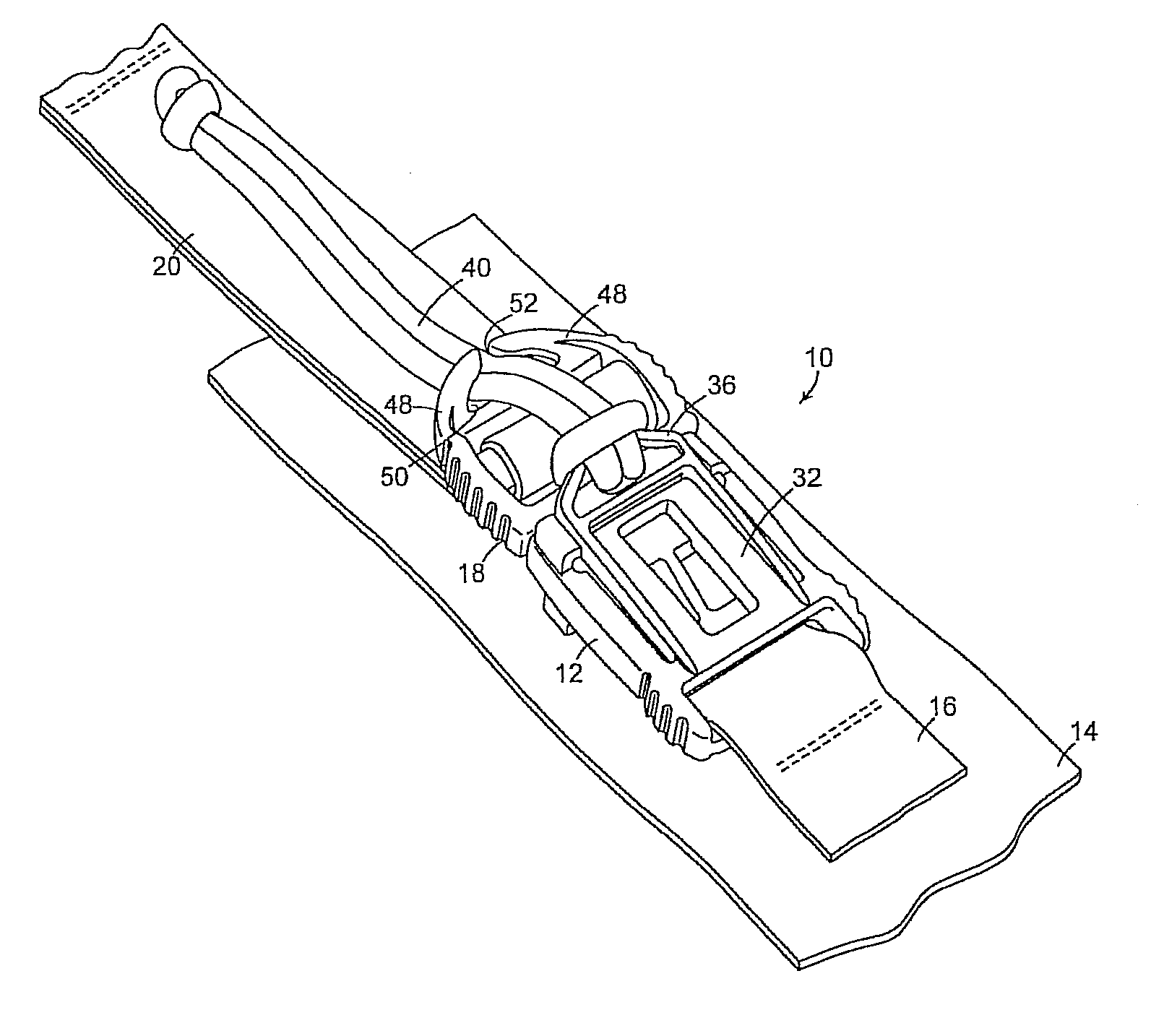
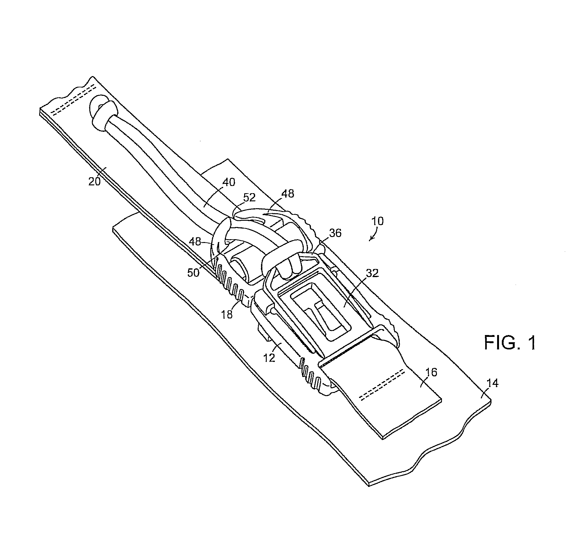
[0018]With reference initially to FIG. 1, a quick release buckle in accordance with the present invention is shown at 10. The buckle comprises a female component 12 connected to a web 14 by a stitched strap 16, and a male component 18 connected to another web 20.

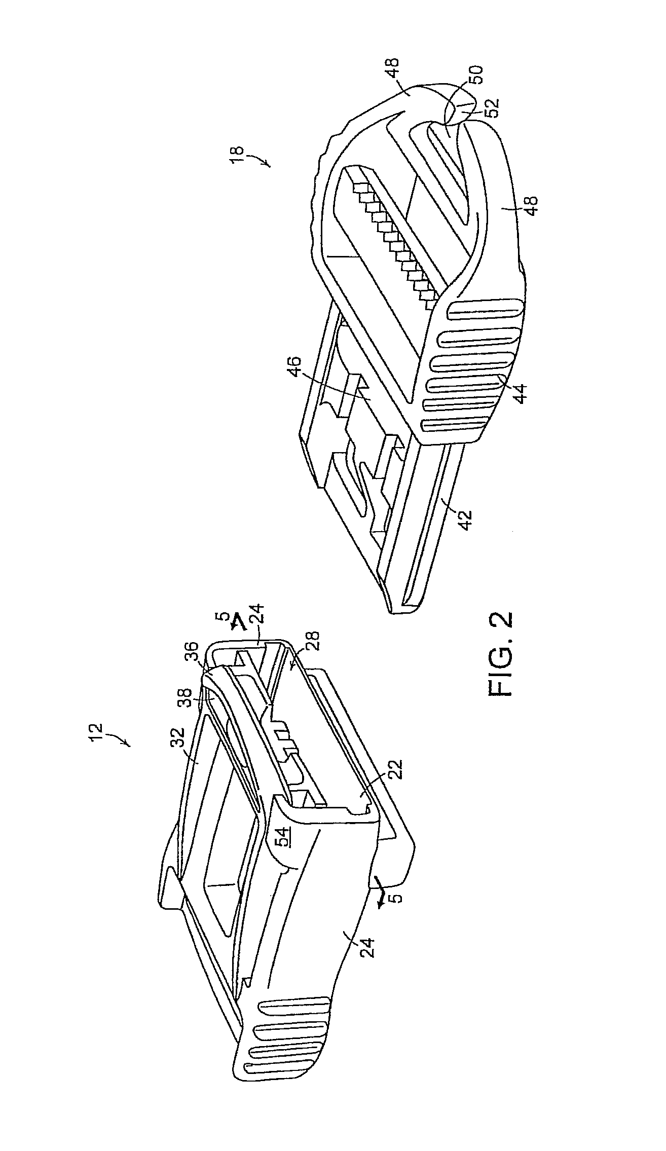
[0019]With reference additionally to the remaining Figures, it will be seen that the female component 12 has a bottom 22 and side walls 24 coacting to define a receiving channel 26 having an access opening 28 at its front end and a rear wall 30 at its rear end. A resiliently deflectable release lever 32 overlies the receiving channel 26 and is supported in cantilever fashion by the rear wall 30. The release lever has a catch 34 on its underside, and a forward end projecting beyond the access opening at the front end of the receiving channel to define a life tab 36. The lift tab 36 is angled upwardly away from the access opening 28, and is provided with an aperture 38 configured and dimensioned to accept dual strands of a lan...


PUM


Abstract

A quick release buckle has male and female components releasably joined in snap engagement. A release lever on the female component provides a means of disengaging the components. The release lever may be actuated either by pulling on a lanyard cord to which it is connected, or by accessing a lift tab projecting from its forward end.

Description

BACKGROUND DISCUSSION[0001]1. Field of the Invention[0002]This invention relates to lanyard style quick-release buckles of the type used to detachably connect straps in backpacks and the like.[0003]2. Description of the Prior Art[0004]Lanyard style quick-release buckles are known, as disclosed for example by U.S. Pat. No. 6,637,083 (Howell). While such buckles are entirely serviceable, experience has indicated that they have a number of shortcomings. For example, their design does not provide a convenient way of parting the interlocked buckle components without using the lanyard. The release levers of the female components are prone to being overstressed and broken by excessive pulling forces on the lanyards. Lanyards are limited to thin webs that are generally sewn into place, and the lanyards are susceptible to inadvertent snagging, resulting in unintended parting of the buckle components.[0005]The objective of the present invention is to obviate or at least significantly minimize...

Claims


Application Information

Patent Timeline
Patent Type & Authority Patents(United States)
IPC IPC(8): A44B11/25A44B11/26
CPCA44B11/2592Y10T24/45529Y10T24/45524Y10T24/45581A44B11/26A44B11/25A44B11/00
Inventor HOWELL, FRANK A.
Owner ILLINOIS TOOL WORKS INC
Why Eureka
Try Eureka