Indirectly prestressed, concrete, roof-ceiling construction with flat soffit

a technology of prestressed concrete and roof-ceiling construction, which is applied in the direction of girders, joists, building roofs, etc., can solve problems such as not achieving proper effects

Inactive Publication Date: 2008-11-11
MARA INST D O O
View PDF9 Cites 42 Cited by
  • Summary
  • Abstract
  • Description
  • Claims
  • Application Information

AI Technical Summary

Benefits of technology

[0005]All the other practical intentions of the present construction include Advantages disclosed by HR-P20000906A that these constructions have when compared to customary roofs and ceilings.

Problems solved by technology

The commonly used prestressing techniques that introduce compressive force into a structural member of a selected geometry cross-section with tendons positioned below the concrete center of gravity would not achieve proper effects when applied to these constructions because of the absence of such an eccentricity.
An achievement of upward deflection of the concrete plate would require lowering of the prestressing tendons below the center of gravity of the overall construction which is unacceptable because it would ruin the idea of the flat soffit.

Method used


Image

  • Indirectly prestressed, concrete, roof-ceiling construction with flat soffit
  • Indirectly prestressed, concrete, roof-ceiling construction with flat soffit
  • Indirectly prestressed, concrete, roof-ceiling construction with flat soffit

Examples


case 1

Case 1

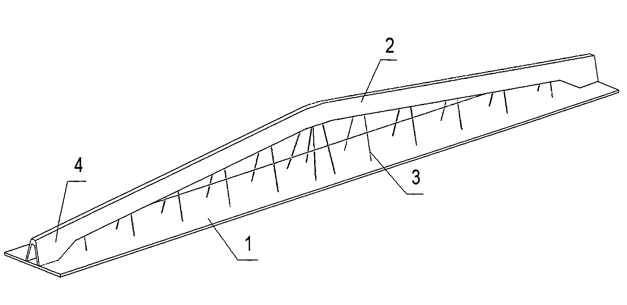
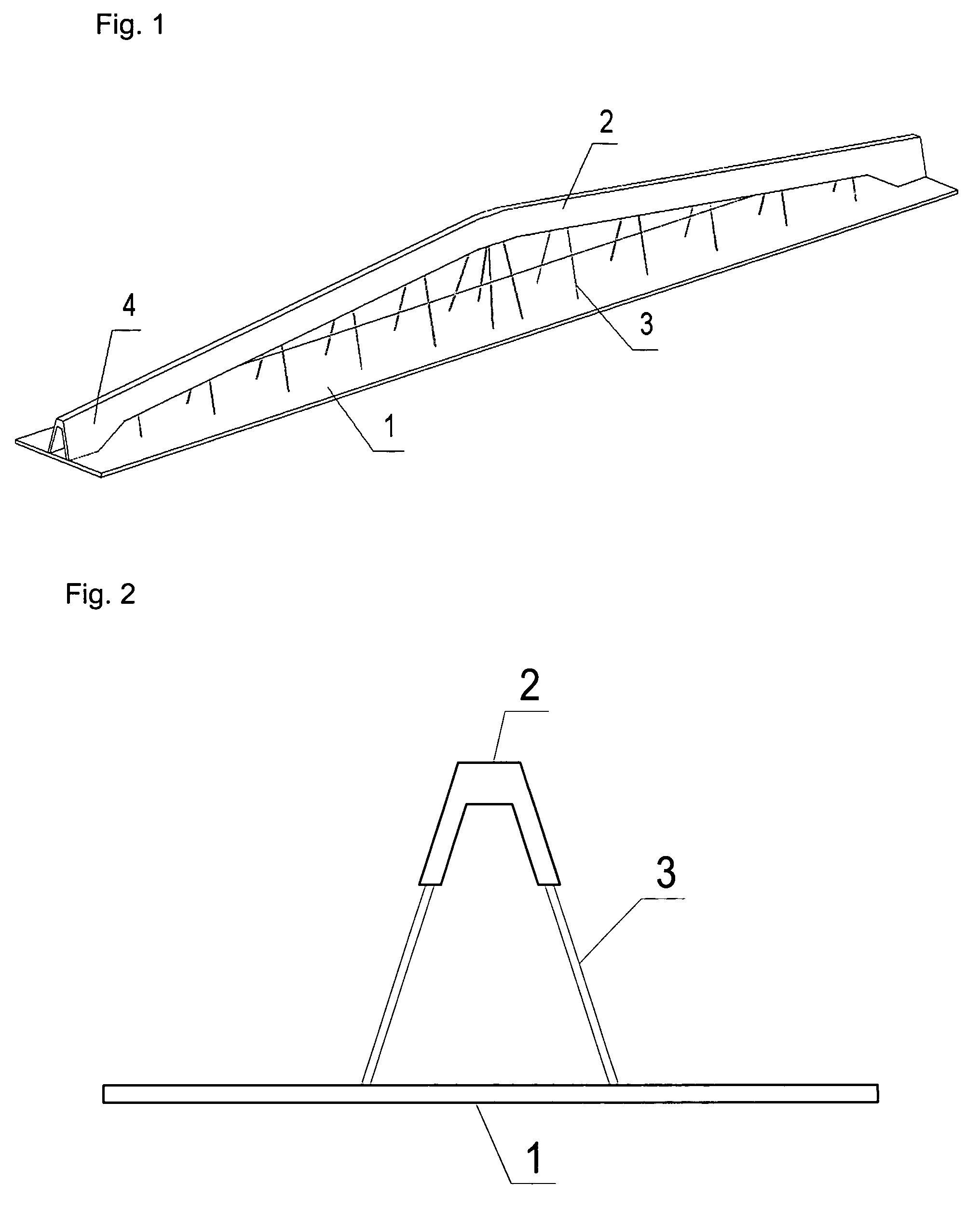
[0026]This case is illustrated in FIG. 1. As it is obvious from the picture, the upper girder (2) is made of one part. Its ends (4) may be considered as short consoles (no matter whether we consider them to be an integral part of the soffit plate or of the upper girder) that are rigidly connected to the soffit plate (1) and are capable of transmitting the bending moments from the upper girder (2). The upper girder (2) is first cast in its own mould and then placed into the soffit plate (1) mould. The prestressing wires are tensioned and anchored at the mould of the soffit plate and the plate (1) is poured. After concrete hardening, the upper girder (2) and the soffit plate (1) become connected by a special detail near supports, the prestressing tendons are released from the mould and the centric prestressing force is introduced into the concrete of the soffit plate (1). The prestressing force shortens the soffit plate (1) causing thereby a mutual displacement of both of the en...

case 2

Case 2

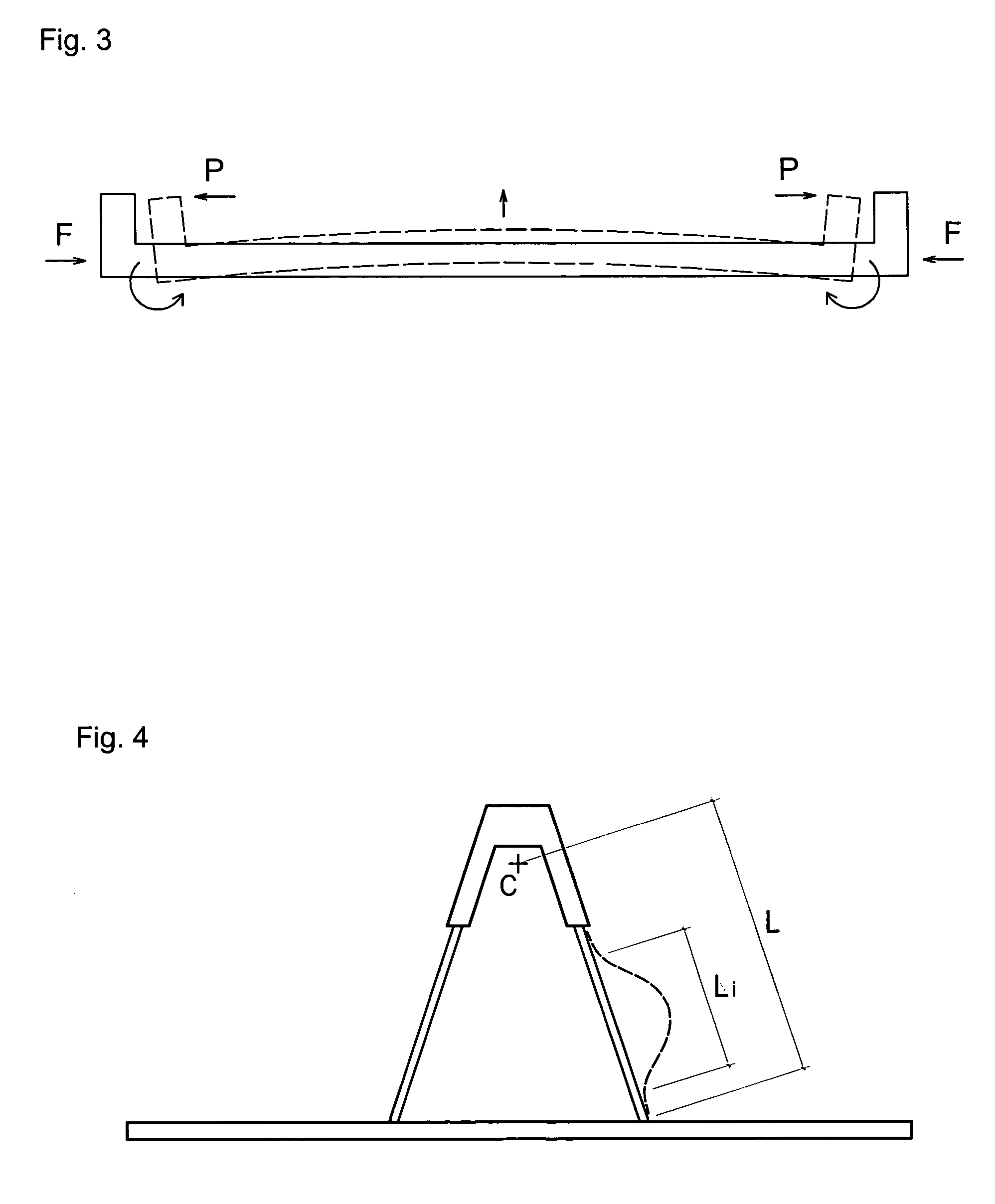
[0027]According to what was described in application HR-P20000906A, the upper girder (2) was made of two parts and prestressed by a double prestressing method, performed in two steps, whereby in the first step the soffit plate (1) is prestressed centrically, before the two separated parts of the upper girder become connected at the midspan, so that the first prestressing does not induce any stresses in disconnected halves of the upper girder. In the other step, at the interrupting point of the upper girder at the midspan a steel wedge driven into a special detail cause both sides pushing apart of the supports, deflecting thereby the soffit plate upwards due to the rotation of its ends.

[0028]In both compared methods the negative bending moment is achieved through rotating ends of the construction to accomplish the upward deflection. But there is a significant difference between CASE 1 and CASE 2 that allows us to prestress the construction with a smaller or larger forces spendi...


PUM


Abstract

An indirectly prestressed concrete roof-ceiling construction is a prefabricated element for constructing large-span industrial buildings. The construction includes a distinctly wide and thin concrete soffit plate and an upper concrete girder of an inverse “V”-shaped cross section, interconnected by slender steel pipe-rods that are used to stabilize the upper girder against lateral buckling and to prevent the plate and the girder from getting closer or further away from each other. Prestressing of the soffit plate causes compression in the upper girder which passively (indirectly) pushes the ends of the construction, acting on some eccentricity over the center of gravity of the cross section, causing rotation of its ends, bending in that way the soffit plate upwards. There are two efficient methods of prestressing these constructions.

Description

[0001]This is a nationalization of PCT / HR02 / 00057 filed Nov. 19, 2002 and published in English.TECHNICAL FIELD[0002]The present invention relates to the construction of roofs of industrial building or other similar buildings of prestressed, reinforced concrete and in particular some steel parts become integral parts of the structure.[0003]The field of the invention is described in IPC Classification E 04 B 1 / 00 that generally relates to constructions or building elements or more particularly group E 04 C 3 / 00 or 3 / 294.BACKGROUND ART[0004]The present invention deals with a specific flat-soffit roof-ceiling construction of an original concept and shape. Although some similarities to trusses or tied arches are obvious the present construction substantially differs from them in the manner of how it works bearing the load. First of all, these constructions are intended to solve both the finished ceiling with flat soffit and the roof construction simultaneously. It is intended also to use...

Claims


Application Information

Patent Timeline
Patent Type & Authority Patents(United States)
IPC IPC(8): E04B1/32E04B7/02E04B7/08E04C3/02E04C3/30E04C5/08E04H12/00E04B1/22E04C3/04E04C3/11E04C3/26E04C3/294
CPCE04B7/022E04C3/11E04C3/26E04C3/294E04C2003/0413E04C2003/0434E04C2003/046E04B5/38E04B7/02
Inventor SKEND{HACEK OVER{HACEK OVER
Owner MARA INST D O O
Why Eureka
Try Eureka