
Torque control for starting system

a starting system and torque control technology, applied in the direction of engine starters, machine/engines, turbine/propulsion engine ignition, etc., can solve the problems of increased drag and high inrush current, and achieve the effect of reducing current draw

Active Publication Date: 2008-11-11
HAMILTON SUNDSTRAND CORP
View PDF2 Cites 23 Cited by
  • Summary
  • Abstract
  • Description
  • Claims
  • Application Information

AI Technical Summary

Benefits of technology

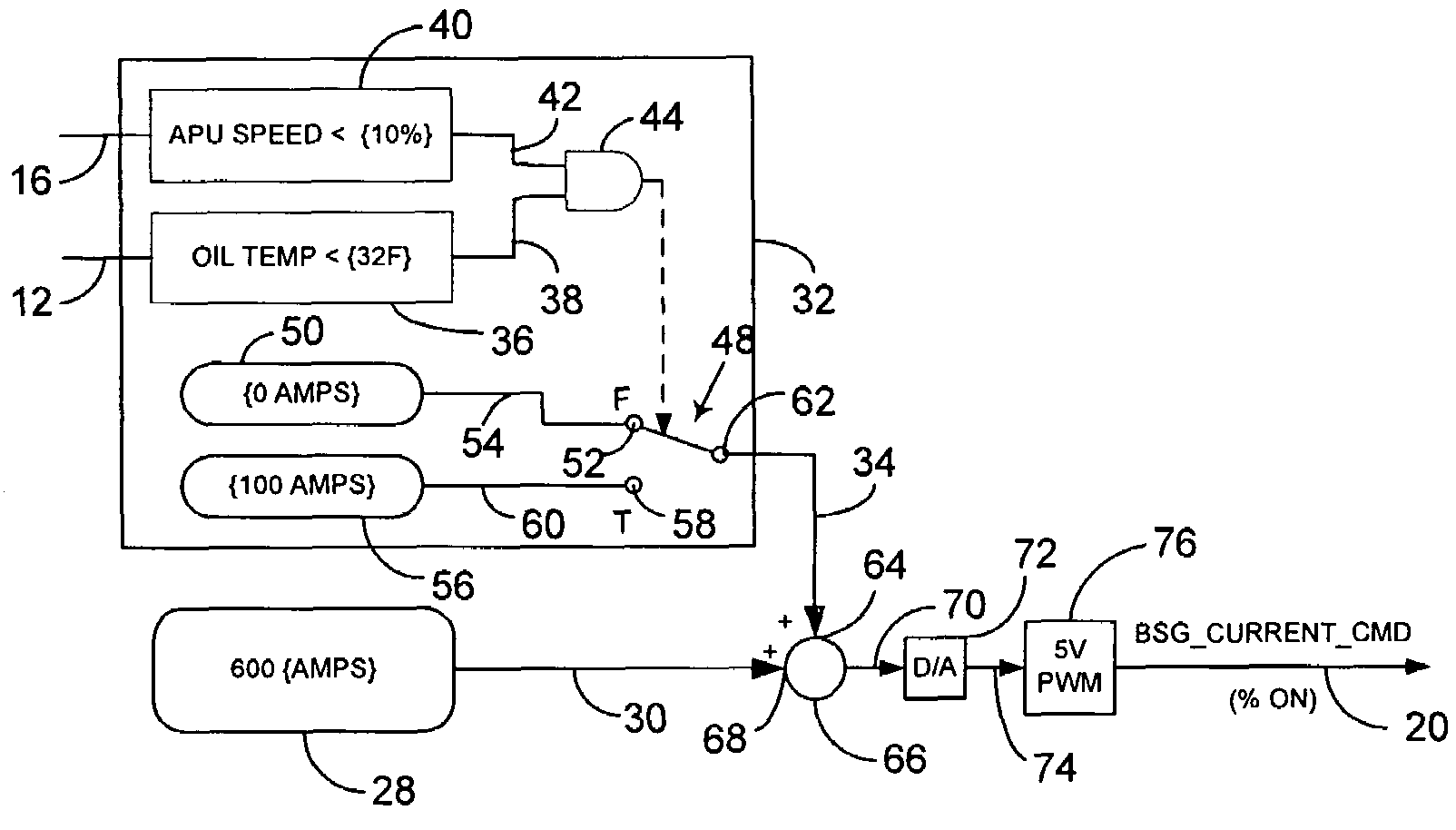
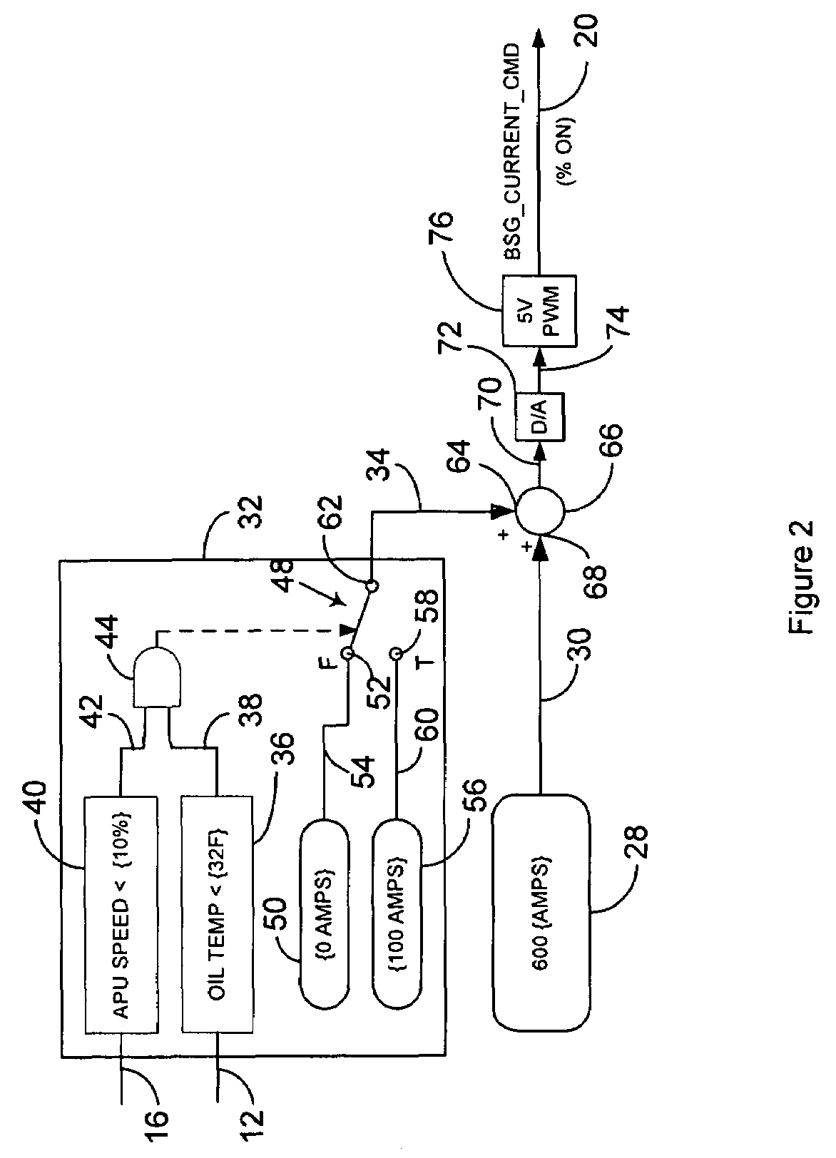
[0007]The invention comprises a start system for a gas turbine engine that delivers starter current according to a schedule selected according to measured engine rotational speed and engine oil temperature. The selected schedule provides enough current so that the start system provides sufficient torque to the engine to overcome drag torque regardless of oil temperature and accelerate the engine at a reasonable rate whilst limiting acceleration to minimise current draw and prevent failed starts.

Problems solved by technology

This is due to several factors, one of which is increased drag due to residual oil left in the APU.
Because the start system generates so much torque, it may cause the APU to accelerate too quickly under average conditions, possibly causing the APU to pass through its light-off window before it has a chance to start, thereby causing a failed start.
It also results in high inrush currents that may require aircraft storage batteries and electrical cables that supply the start system in order to avoid large electrical potential drops.

Method used


Image

  • Torque control for starting system
  • Torque control for starting system
  • Torque control for starting system

Examples


Embodiment Construction

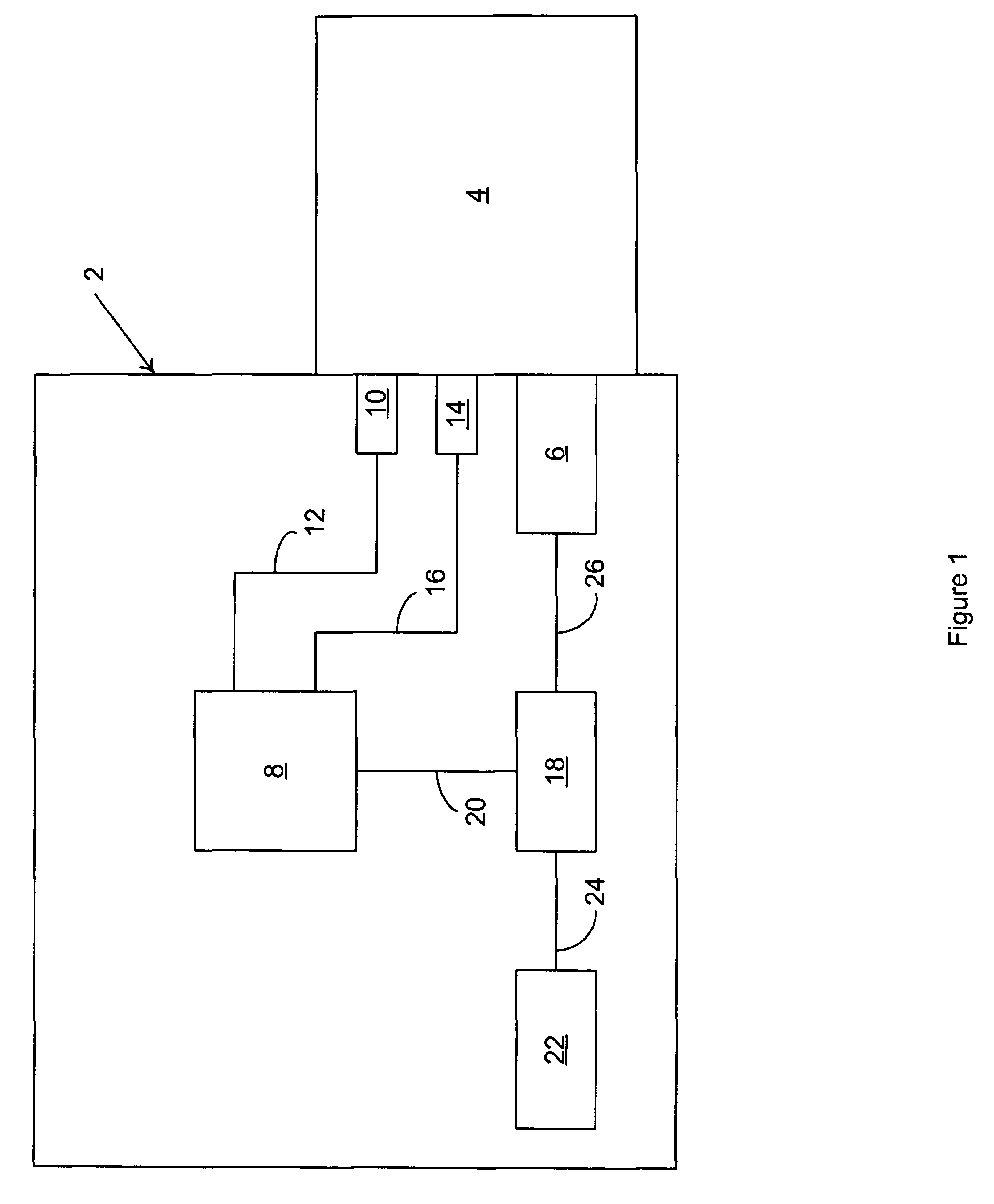
[0011]Referring to FIG. 1, the invention comprises a start system 2 for a gas turbine engine 4, such as an APU, that has a starter 6 with torque output responsive to current input, such as a brushless DC motor. The starter 6 may actually serve as a starter generator or dedicated starter motor. An electronic controller 8, such as a full authority digital electronic controller (FADEC), may monitor temperature of the oil in the gas turbine engine 4, such as with an oil temperature signal provided by an engine oil temperature sensor 10 connected to it by way of an engine oil temperature data line 12, and rotational speed of the gas turbine engine 4, such as with a rotational speed signal provided by a rotational speed sensor 14 connected to it by way of a rotational speed data line 16. Of course, the electronic controller 8 may derive engine oil temperature and engine rotational speed by other means if convenient.

[0012]The electronic controller 8 may provide a schedule of current levels...


PUM


Abstract

A start system for a gas turbine engine delivers starter current according to a schedule selected according to measured rotational speed and oil temperature of the gas turbine engine.

Description

FIELD OF THE INVENTION[0001]The invention relates to a starting system for a gas turbine engine, and more particularly to such a starting system that has a torque control responsive to environmental conditions.BACKGROUND OF THE INVENTION[0002]Modern aircraft secondary power systems have a gas turbine powered auxiliary power unit (APU) on board to provide electrical, hydraulic and pneumatic power for operating systems aboard the aircraft when the propulsion engines are shut down as well as to provide power for starting the propulsion engines. Typically, pneumatic power, provided by a load compressor within the APU, is used to start the propulsion engines.[0003]An electrical start system that comprises a starter or starter generator initiates ignition of the APU. The start system must generate enough torque to overcome drag or resisting torque of the APU and to accelerate the APU to achieve light off and self-sustaining rotational speed. The drag torque of an APU increases as the temp...

Claims


Application Information

Patent Timeline
Patent Type & Authority Patents(United States)
IPC IPC(8): F02C7/275
CPCF01D25/18F02C7/268F02C7/32F05D2270/304F05D2270/303
Inventor SCHMIDT, DENNIS E.RIPLEY, DAVID L.COGSDILL, LAWRENCE A.
Owner HAMILTON SUNDSTRAND CORP
Learn More