
Ink jet printhead having a movable redundant array of nozzles

a technology of a nozzle array and a printhead is applied in the field ofink jet printers, which can solve the problems of limiting the usefulness of high-quality production applications, streaks, and insufficient array of channels in a single die assembly to cover the full width of a recording medium page, and achieve the effect of high-quality printing

Active Publication Date: 2008-11-11
XEROX CORP
View PDF9 Cites 36 Cited by
  • Summary
  • Abstract
  • Description
  • Claims
  • Application Information

AI Technical Summary

Benefits of technology

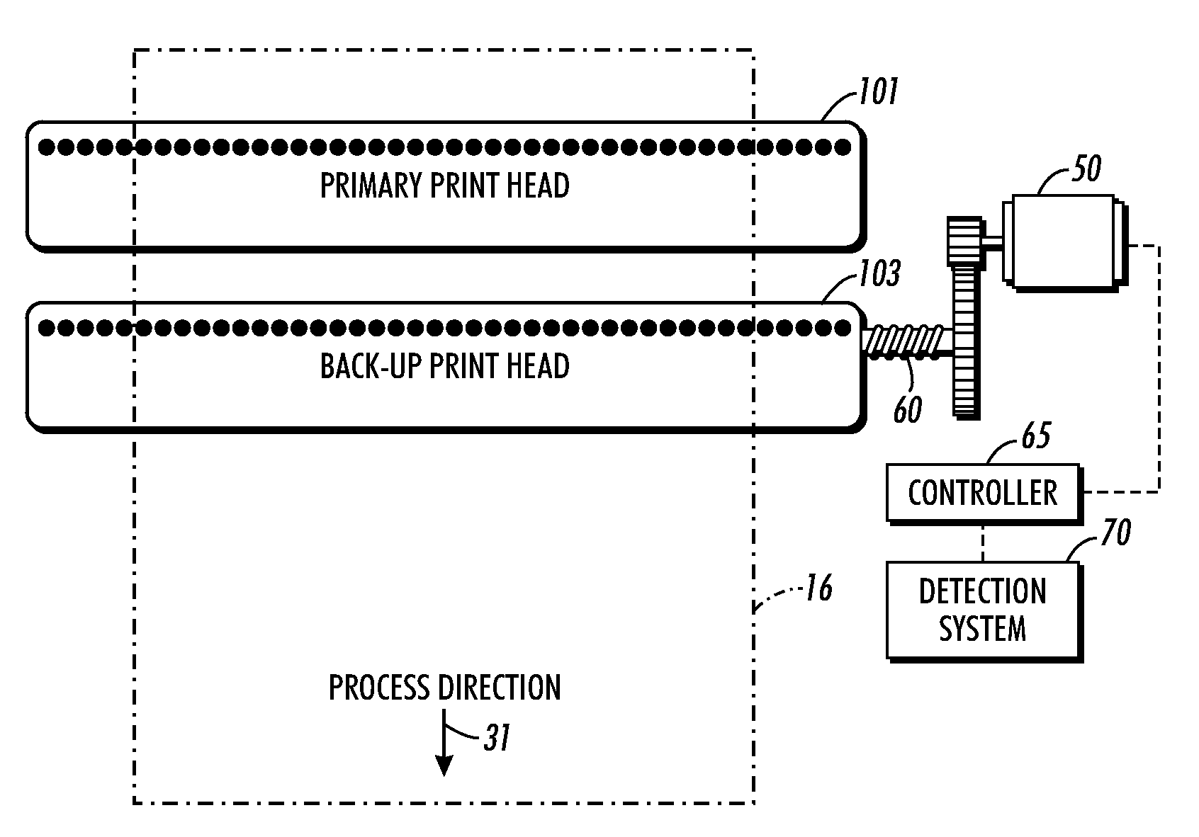
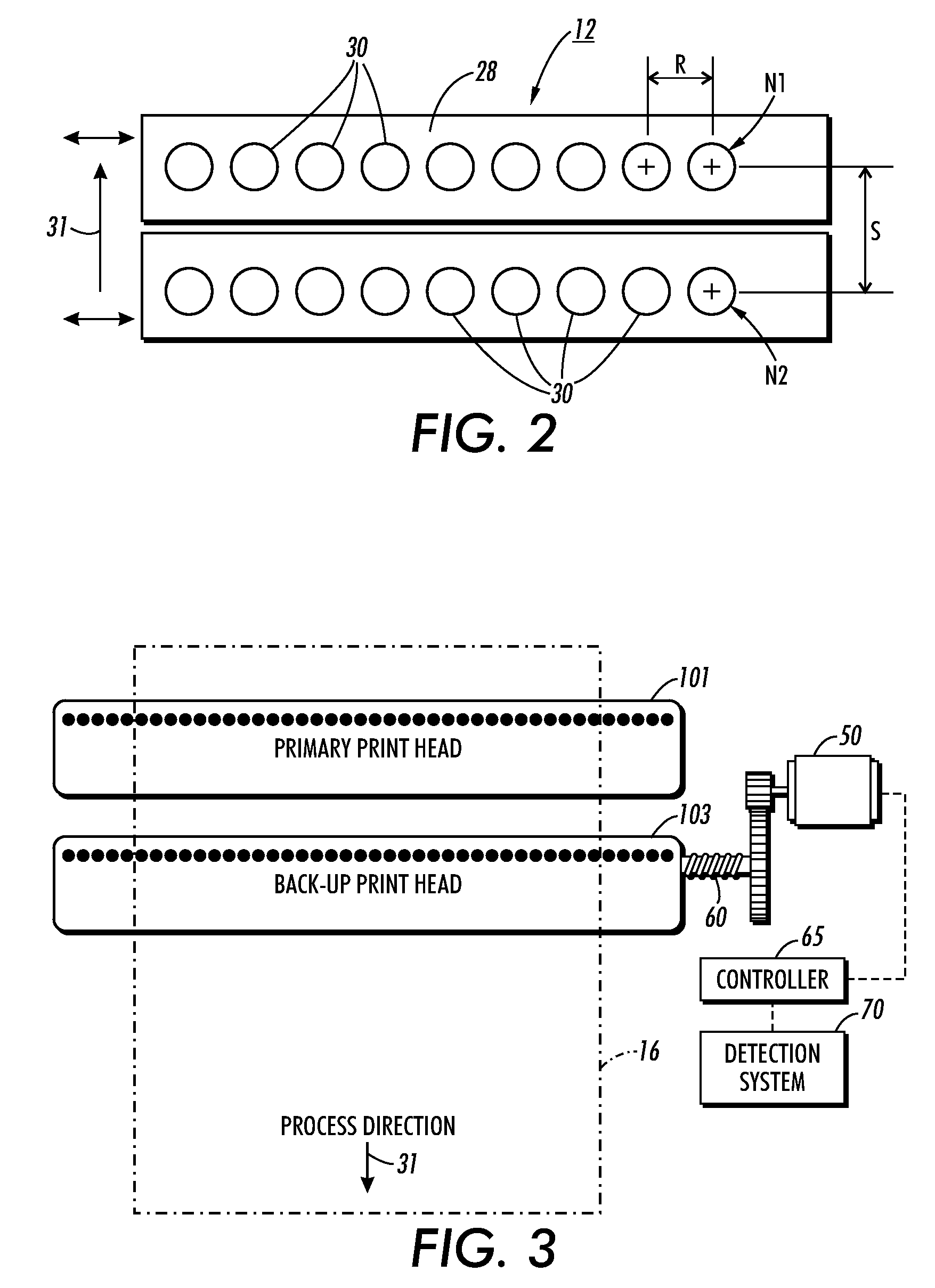
[0001]An exemplary embodiment of this application relates to an ink jet printer having a printhead and controller that enables high-quality printing. More particularly, the exemplary embodiment relates to an ink jet printer with a set of two printhead arrays in which the second array of nozzles is movable with respect to a first array of nozzles in a cross process direction with the individual nozzles in one array being positioned in alignment or close to alignment with corresponding nozzles in the second array in the scanning or process direction.

Problems solved by technology

The array of channels in a single die assembly is not sufficient to cover the full width of a page of recording medium, such as, for example, a standard sheet of paper.
A problem with ink jet print printers is random failures of ink jet print heads due to nozzle contamination which limits their usefulness in high quality production applications.
In the single-pass systems needed for high-speed production systems even weak or miss-directed jets may result in visible image defects in the form of streaks.
Since these failures are unpredictable by nature, some form of regular output monitoring is needed to ensure that occurrences are detected before large portions of a job are affected.
Even with such monitoring, the productivity impacts of stopping the press to change or purge heads could be significant.
The use of ink jet systems for high quality production printing applications has been very limited.
Web cleaners and air flow techniques have been used to minimize the amount of paper dust that comes in contact with the printheads, but the random failures of ink jet printheads still remain.

Method used


Image

  • Ink jet printhead having a movable redundant array of nozzles
  • Ink jet printhead having a movable redundant array of nozzles
  • Ink jet printhead having a movable redundant array of nozzles

Examples


Embodiment Construction

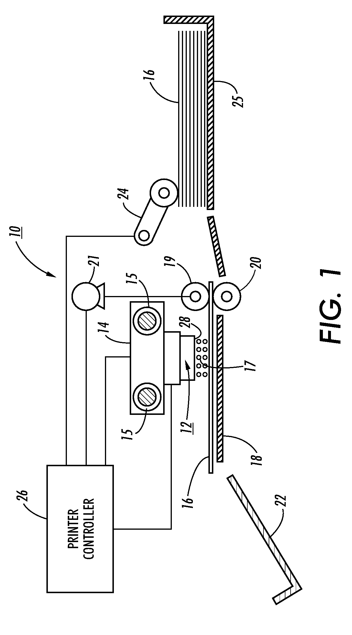
[0017]In FIG. 1, a schematic representation of a carriage type thermal ink jet printer 10 is shown in a side elevation view. The ink jet printer 10 employs a translating thermal ink jet printhead 12 that has a roof shooter structure mounted on a carriage 14 which travels back and forth across the recording medium 16 on guide rails 15. In the orientation of the printhead shown in FIG. 1, the printhead translation is along guide rails that are normal to the surface of the drawing. Alternatively, the printer 10 may employ a fixed full width printhead (not shown) wherein the recording medium is continually moved there past at a constant or variable speed by feed rollers (not shown).

[0018]The printhead 12 ejects ink droplets 17 onto the recording medium 16 residing on printing platen 18 one swath at a time and feed rollers 19 and 20, one of which is driven by an electric motor 21, is capable of precise motion quality. The electric motor 21 is used both to register and step the recording ...


PUM


Abstract

There is provided a printhead for an ink jet printer, including a primary and a secondary array of nozzles in the printhead, the nozzles in the primary array of nozzles being in alignment with the nozzles in the secondary array of nozzles in a printing process direction; detection system for detecting defective nozzles in both the primary array of nozzles and in the secondary array of nozzles; a first mode operation having means for selectively activating nozzles in the secondary array of nozzles that are in alignment with defective nozzles in the primary array of nozzles; and a second mode of operation having means, responsive to the detecting means, for translating the secondary array of nozzles in relation to the primary array of nozzles along a path to a first position to realigned the nozzles in the primary array of nozzles to nozzles in the secondary array of nozzles if defective nozzles are aligned in both the primary and the secondary array of nozzles.

Description

BACKGROUND AND SUMMARY[0001]An exemplary embodiment of this application relates to an ink jet printer having a printhead and controller that enables high-quality printing. More particularly, the exemplary embodiment relates to an ink jet printer with a set of two printhead arrays in which the second array of nozzles is movable with respect to a first array of nozzles in a cross process direction with the individual nozzles in one array being positioned in alignment or close to alignment with corresponding nozzles in the second array in the scanning or process direction.[0002]Droplet-on-demand ink jet printing systems eject ink droplets from printhead nozzles in response to pressure pulses generated within the printhead by either piezoelectric devices or thermal transducers, such as resistors. The ejected ink droplets are propelled to specific locations on a recording medium, commonly referred to as pixels, where each ink droplet forms a spot on the recording medium. The printheads c...

Claims


Application Information

Patent Timeline
Patent Type & Authority Patents(United States)
IPC IPC(8): B41J29/393
CPCB41J29/393B41J2/2139B41J2/045B41J2/01B41J29/38
Inventor NEWELL, ROGER A
Owner XEROX CORP
Learn More