Hinge

a technology of hinges and hinges, applied in the field of hinges, can solve the problems of difficult and laborious rotation of pivotal pins relative to sleeves, and achieve the effect of reducing shak

Inactive Publication Date: 2008-11-18
SHIN ZU SHING
View PDF11 Cites 32 Cited by
  • Summary
  • Abstract
  • Description
  • Claims
  • Application Information

AI Technical Summary

Benefits of technology

[0006]The objective of the present invention is to provide a hinge that can reduce the shake between the reed pipes and the jacket, and make the cover can be rotated smoothly in relative to the base of the electrical appliance.

Problems solved by technology

Because the resilient sleeves are expanded by the pivotal pin to provide a clamping effect to the pivotal pin and hold the cover in place, to rotate the pivotal pin relative to the sleeve is difficult and laborious.

Method used


Image

  • Hinge
  • Hinge
  • Hinge

Examples


Embodiment Construction

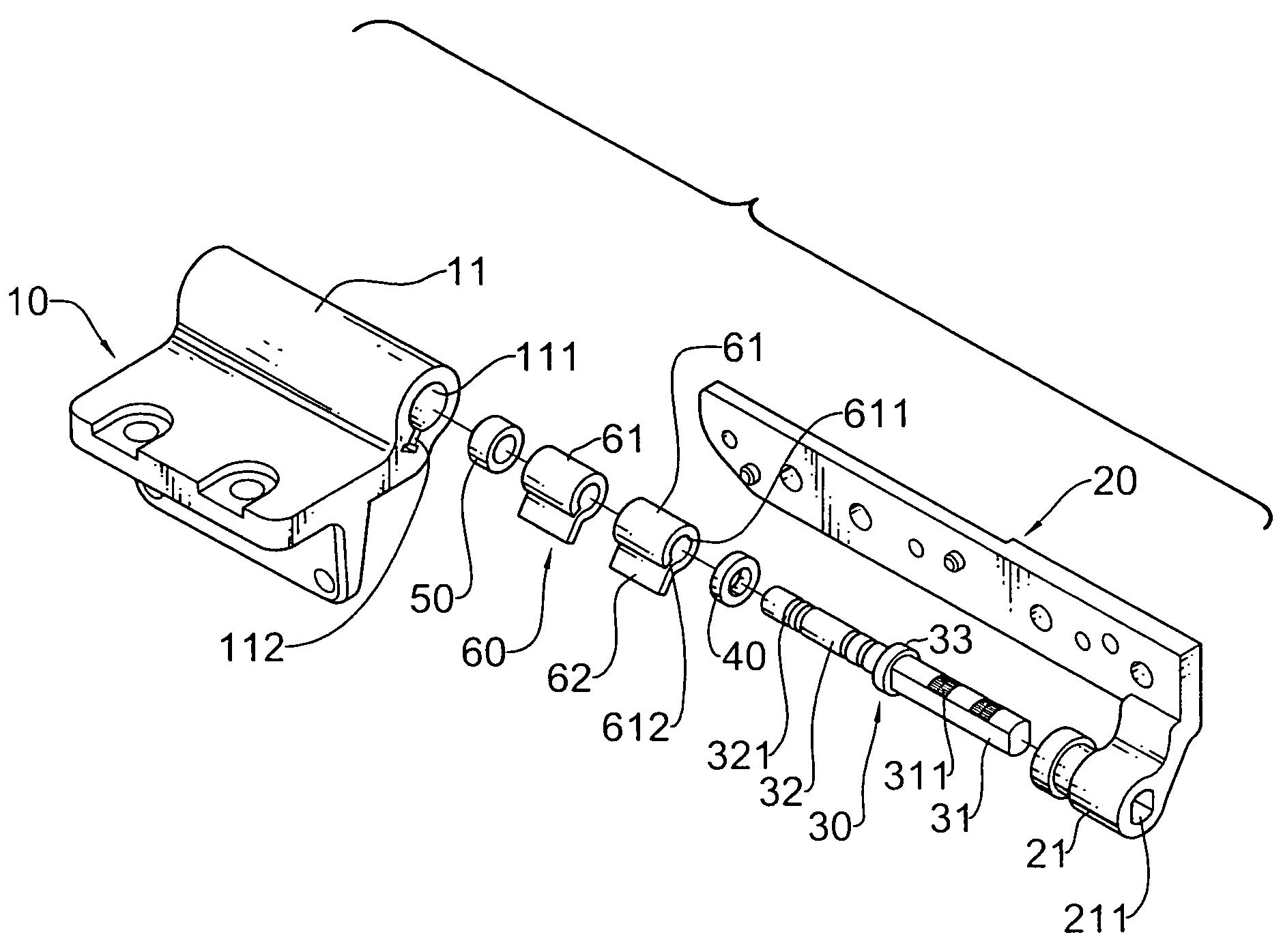
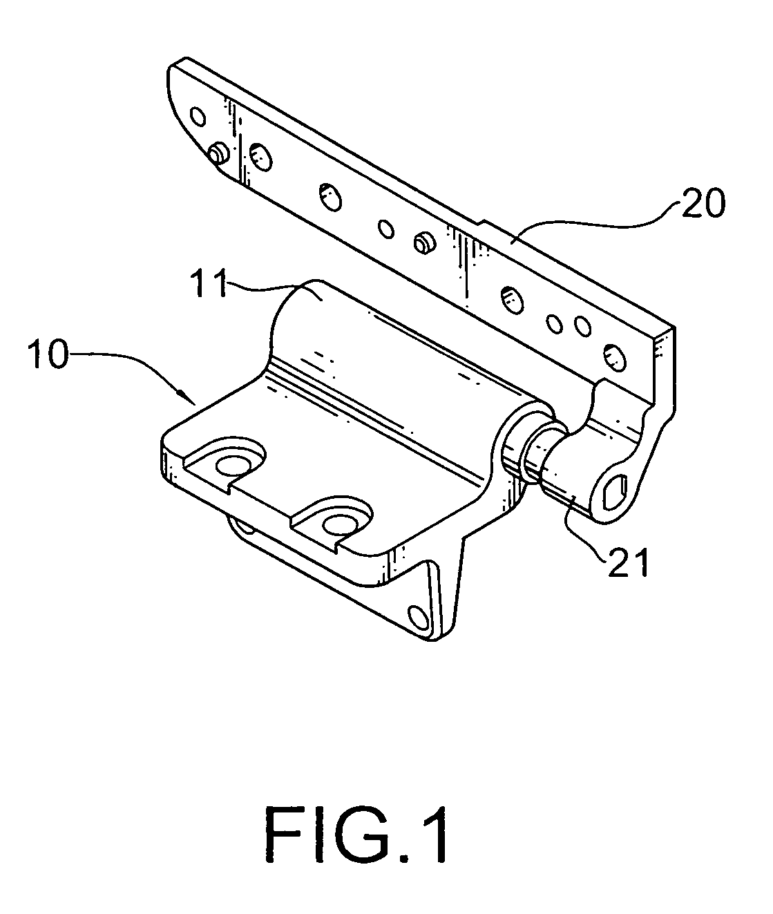
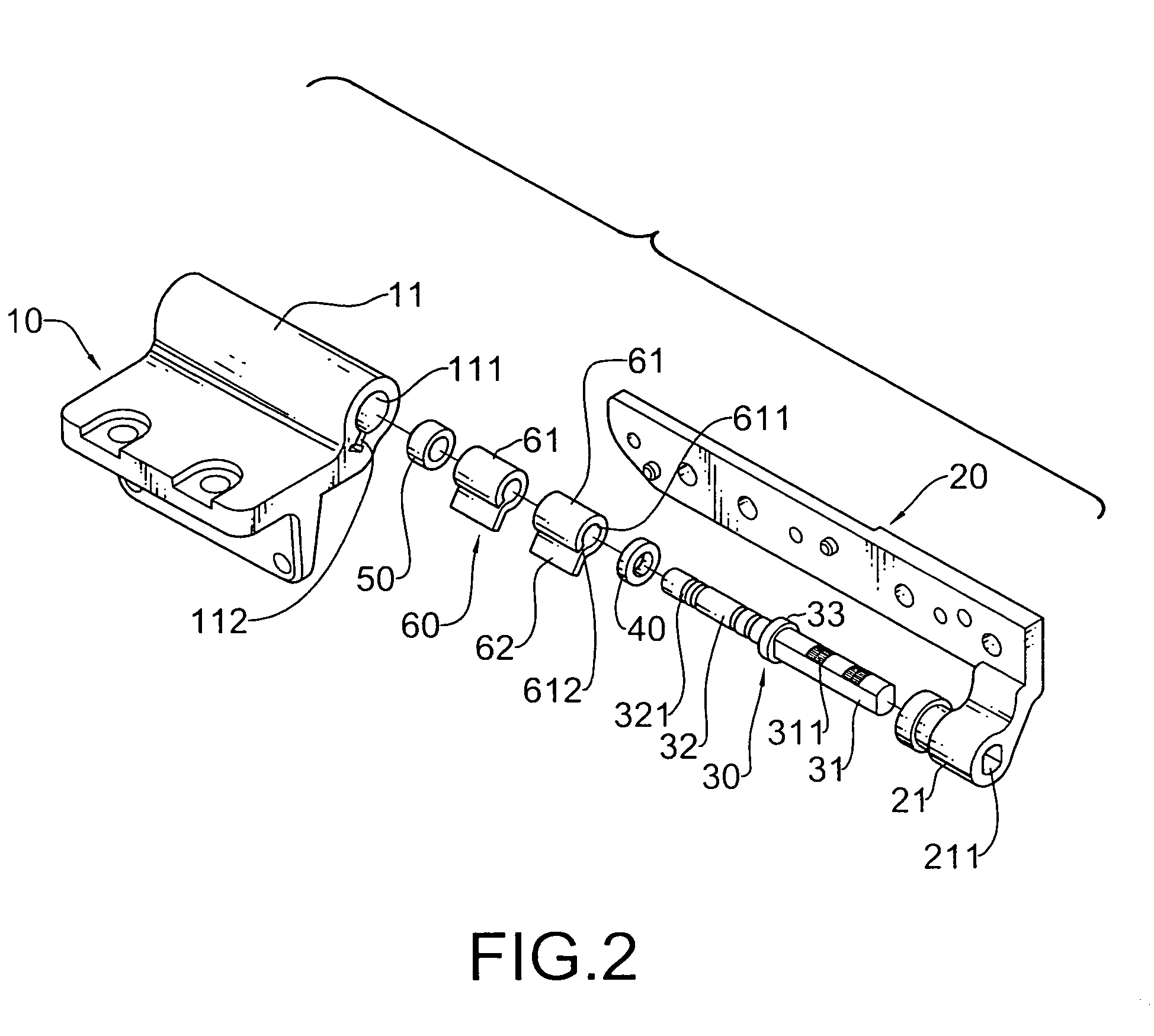
[0017]With reference to FIGS. 1 to 7, a hinge in accordance with the present invention comprises a positioning bracket (10), a rotating bracket (20), a pivotal pin (30), a washer (40), a mounting ring (50) and two resilient sleeves (60).

[0018]The positioning bracket (10) has a side and a sleeve (11). The sleeve (11) is formed in the side of the positioning bracket (10) and has a through hole (111) and an elongating groove (112). The through hole (111) is formed axially through the sleeve (11). The elongating groove (112) is formed axially through the sleeve (11), communicates with the through hole (111) and can be I-shaped or T-shaped in cross section.

[0019]The rotating bracket (20) is a plate and has a proximal end, a distal end and a connecting segment (21). The connecting segment (21) protrudes out from the proximal end of the rotating bracket (20), comprises a mounting hole (211) and may have an inner wall and multiple indents. The mounting hole (211) is formed axially through t...


PUM


Abstract

A hinge has a positioning bracket, a rotating bracket, a pivotal pin, a washer, a mounting ring and two resilient sleeves. The positioning bracket has a sleeve. The sleeve has a through hole and an elongating groove. The rotating bracket has a connecting segment. The pivotal pin is attached to the rotating bracket and has a mounting shaft, a connecting shaft and a head. The washer and the mounting ring are mounted around the connecting shaft of the pivotal pin. The resilient sleeves are mounted around the connecting shaft, are mounted in the through hole of the sleeve and each resilient sleeve has a sleeve segment and a mounting slice. The sleeve segment has a through hole and a gap. The mounting slice is formed on the sleeve segment near the gap and is inserted into the elongating groove.

Description

BACKGROUND OF THE INVENTION[0001]1. Field of the Invention[0002]The present invention relates to a hinge, especially to a hinge mounted in an electrical appliance to allow a cover of the electrical appliance rotating relative to a base of the electrical appliance.[0003]2. Description of the Related Art[0004]Electrical appliances such as notebook computers comprise a cover, a base and a hinge. The hinge is usually mounted pivotally between the cover and the base to allow the cover rotating relative to the base. The conventional hinge comprises multiple resilient sleeves, a sleeve and a pivotal pin. Each resilient sleeve is elastic and is tubular and has an end, a gap, an extending segment and an inner diameter. The gap is formed in the end of the resilient sleeve. The extending segment extends radially from the resilient sleeve near the gap. The sleeve is hollow and is mounted around the resilient sleeves and is attached to the base of the electrical appliance. The pivotal pin extend...

Claims


Application Information

Patent Timeline
Patent Type & Authority Patents(United States)
IPC IPC(8): E05D11/08E05D11/02G06F1/16H05K7/16
CPCE05D11/02E05D11/082G06F1/1616G06F1/1681E05D2005/102Y10T16/52Y10T16/54038E05Y2900/606
Inventor LU, SHENG-NANHSU, JIA-HAO
Owner SHIN ZU SHING
Why Eureka
Try Eureka