Counter-rotating turbine engine including a gearbox

Active Publication Date: 2008-11-18
ROLLS ROYCE PLC
View PDF19 Cites 106 Cited by
  • Summary
  • Abstract
  • Description
  • Claims
  • Application Information

AI Technical Summary

Benefits of technology

[0018]Possibly, an additional turbine upstream of the first turbine is provided for further work distribution through the a

Problems solved by technology

However, it will be understood through use of the contra-rotating casings there may be additional problems.
In short, the systems that do not use a gearbox generally create additional configurational mechanical complexity and may also significantly limit the maximum speed of rotation for th

Method used


Image

  • Counter-rotating turbine engine including a gearbox
  • Counter-rotating turbine engine including a gearbox
  • Counter-rotating turbine engine including a gearbox

Examples


Embodiment Construction

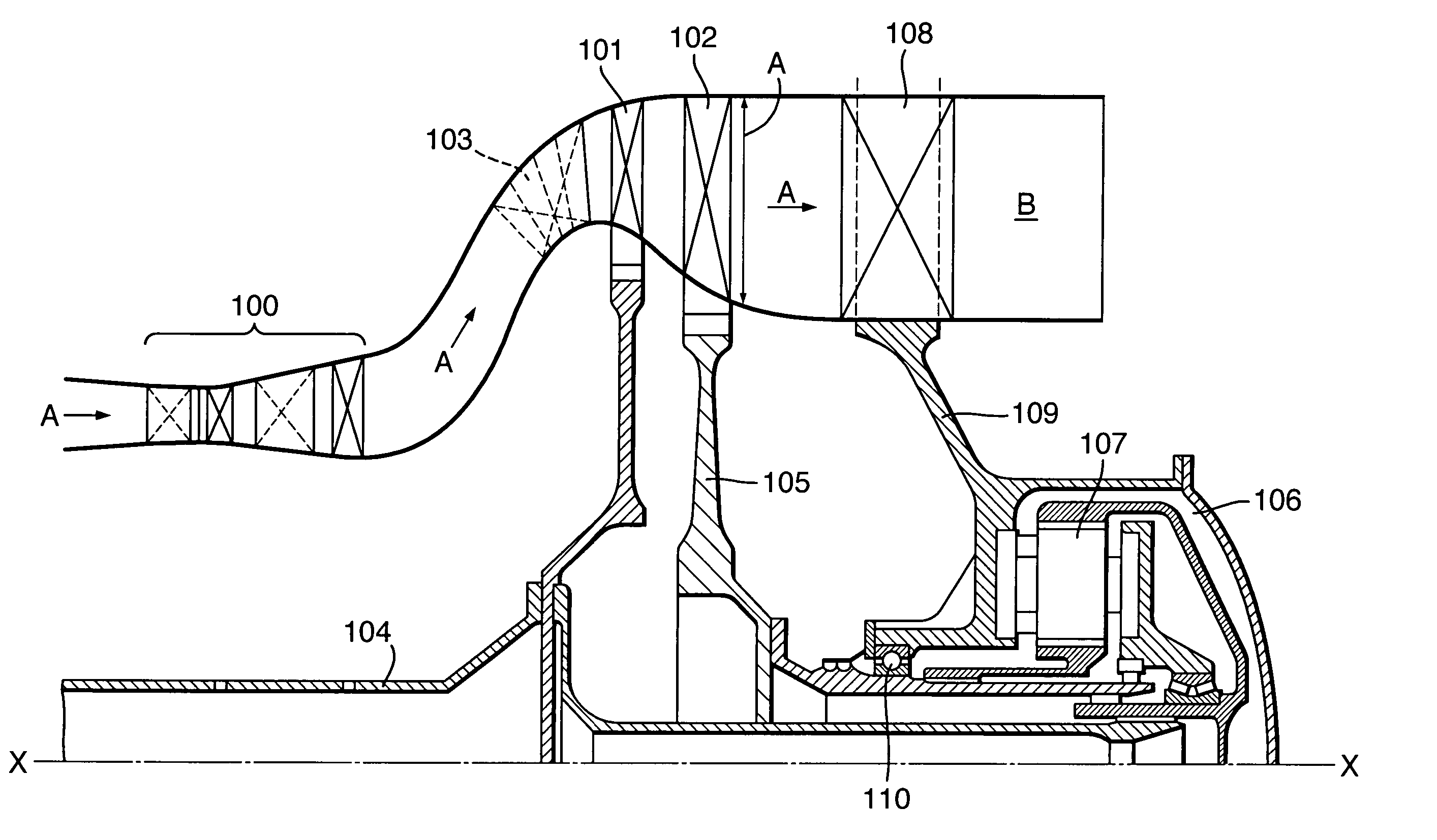
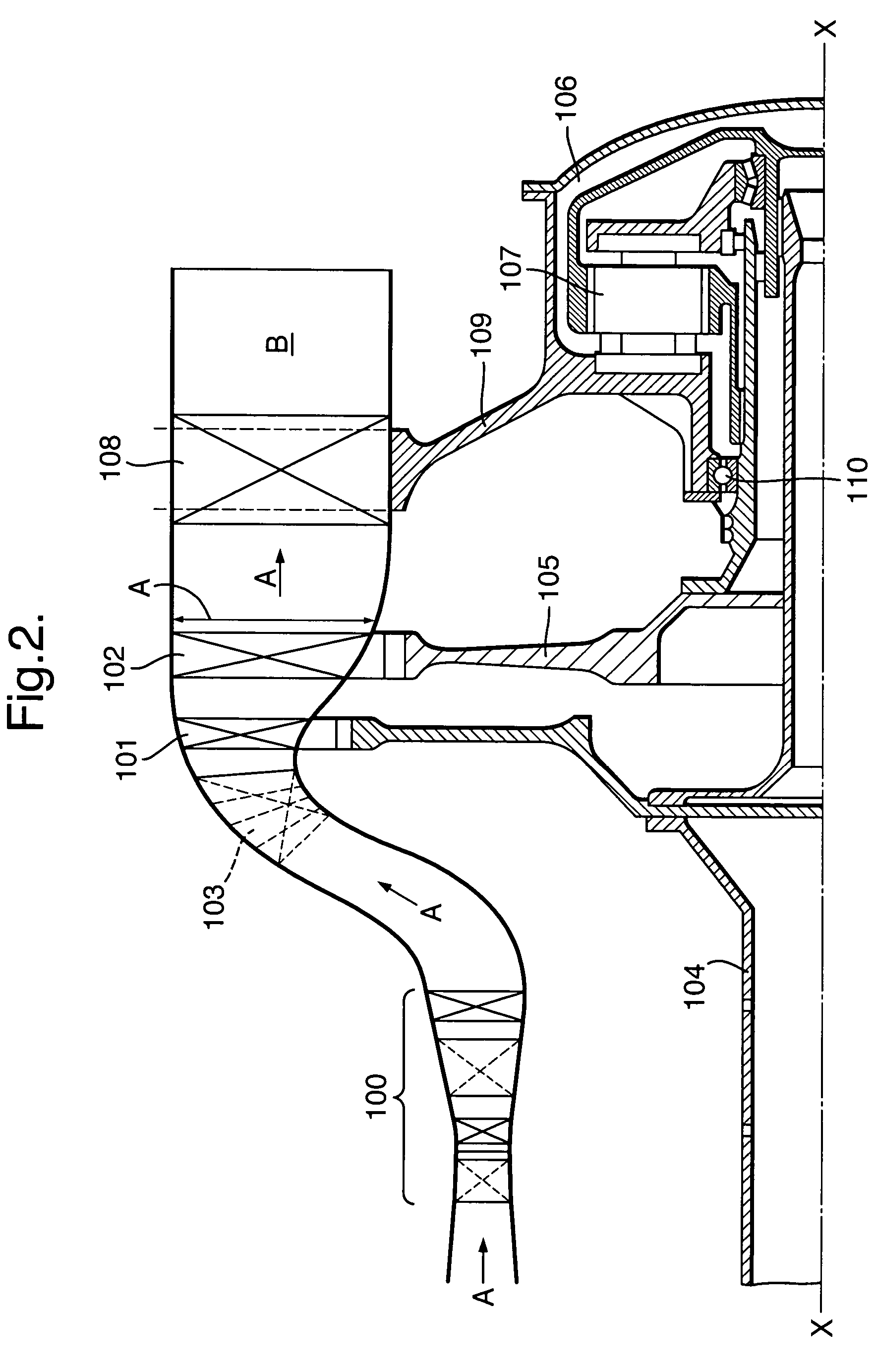
[0022]An embodiment of the present invention will now be described by way of example with reference to FIG. 2 illustrating a schematic half cross-section of a turbine engine arrangement in accordance with the present invention.

[0023]Referring to FIG. 2 providing a part schematic cross-section of a turbine engine arrangement in accordance with the present invention. Thus, it can be seen high pressure turbines 100 are present upstream of a first low pressure turbine 101 and a second low pressure turbine 102. Upstream of the first turbine 101 is located a guide vane assembly 103 such that a gas flow in the direction of arrowhead A passes through the high pressure turbines 100 and is then appropriately orientated and presented to the first turbine 101 by the guide vane assembly 103. It will be appreciated that the arrangement is generally symmetrical and cylindrical such that the turbines 101, 102 rotate about a central axis X-X.

[0024]The first turbine 101 is secured to a first shaft 10...


PUM


Abstract

A turbine engine arrangement is provided in which contra rotating shafts 104, 105 are respectively secured to a fan and a gearbox 106 which is also coupled to the shaft 104. In such circumstances the relative rotational speed ratio between the shafts 104, 105 can be determined with a first low pressure turbine 101 secured to the first shaft 104 arranged to rotate at a lower speed but provide high work whilst a second low pressure turbine 102 secured to the second shaft 105 rotates at a higher speed governed by the gearbox 106. By such an arrangement a smaller gearbox 106 may be used as less power is transferred through that gearbox 106 than with previous arrangements. By contra rotation of the turbines 101, 102 a lower flow deflection guide vane assembly 103 may be used and a further stator/guide vane assembly is not required between the turbines 101, 102.

Description

BACKGROUND[0001]1. Field of the Invention[0002]The present invention relates to turbine engine arrangements and more particularly to a contra rotating turbine engine arrangement.[0003]2. Description of Related Art[0004]Operation of turbine engines is well known. Referring to FIG. 1, a gas turbine engine is generally indicated at 10 and comprises, in axial flow series, an air intake 11, a propulsive fan 12, an intermediate pressure compressor 13, a high pressure compressor 14, a combustor 15, a turbine arrangement comprising a high pressure turbine 16, an intermediate pressure turbine 17 and a low pressure turbine 18, and an exhaust nozzle 19.[0005]The gas turbine engine 10 operates in a conventional manner so that air entering the intake 11 is accelerated by the fan 12 which produce two air flows: a first air flow into the intermediate pressure compressor 13 and a second air flow which provides propulsive thrust. The intermediate pressure compressor compresses the air flow directed ...

Claims


Application Information

Patent Timeline
IPC IPC(8): F02K3/00F01D1/24F01D1/26F02C3/067F02C3/073F02K3/06F02K3/072
CPCF01D1/26F02C3/067F02C3/073F02K3/072Y02T50/671Y02T50/60
Inventor TAYLOR, MARK D.HARVEY, NEIL W.
Owner ROLLS ROYCE PLC
Why Eureka
Try Eureka