Method and apparatus for clamping surgical wires or cables

a surgical wire or cable technology, applied in the field of surgical methods and apparatus for clamping cables or wires, can solve the problems of reducing the clamp reducing the clamping efficiency of the device, so as to improve the clamping ability of the device

Inactive Publication Date: 2008-11-18
PIONEER SURGICAL TECH INC
View PDF19 Cites 21 Cited by
  • Summary
  • Abstract
  • Description
  • Claims
  • Application Information

AI Technical Summary

Benefits of technology

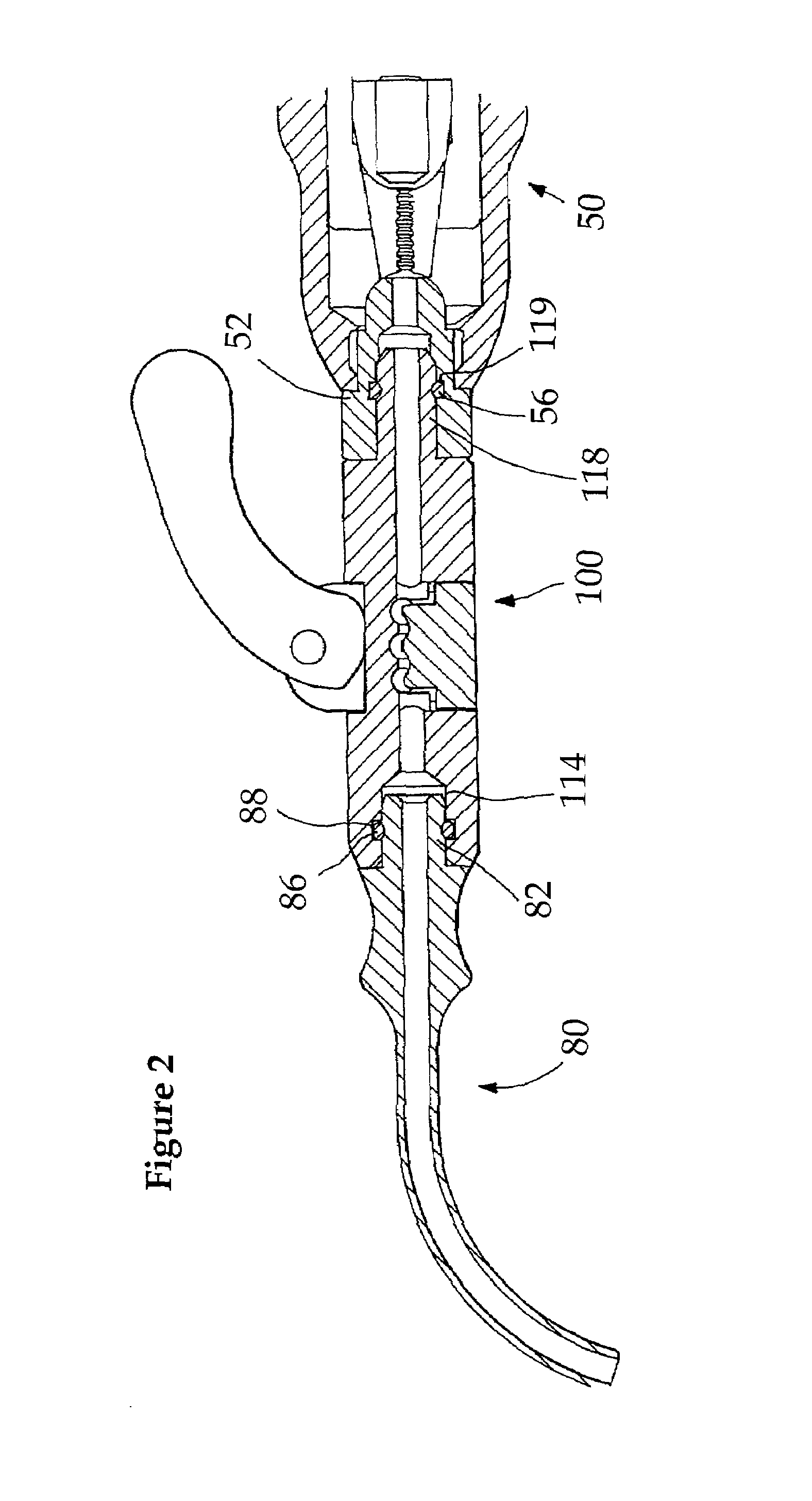
[0008]The aforementioned problems are addressed by the present invention, which in an exemplary embodiment provides a clamping device incorporating a cable housing, a cable bore defined therein and a pivotable lever to move a clamping member relative to the housing. In various aspects of the invention, the clamping member is defined by a saddle member and / or a platen adapted to move relative to the housing for clamping an elongate member within the cable housing. The saddle member, platen or housing may further be equipped with an engaging surface adapted to enhance the clamping ability of the device by, for example, redirecting the elongate member to a non-linear path at the point of clamping. The pivotable lever cooperates with a lever interface surface so that movement of the lever results in movement of the clamping member to engage the elongate member within the housing. In other aspects of the invention, the face of the lever may be a faceted cam surface or a generally smooth, oblong lobe with or without one or more facets, while the lever interface surface, may be a generally smooth surface or a cam surface having at least two discrete surface areas. In this way, the combination of lever and lever interface surface further cooperate to define locking positions associated with optimal clamping forces applied to elongate members of various sizes.

Problems solved by technology

Thus, as the cam lever is operated to clamp the cable, the clamping force is applied to a relatively small area of the cable surface and the cable is subjected to potentially damaging shear and compressive forces.
This may result in local weakening of the cable, which is undesirable especially since the cable may be in place for long periods of time and subject to repetitive stresses and any weakened portion will represent the potential for failure of the cable.
Another problem with cable clamps of the prior art is that they do not provide for efficient and risk-free operation with a variety of different sized cables.
When used with larger cable diameters, prior art devices may apply excessive and damaging forces to the cable when the cam is moved to the clamping position.
Yet another shortcoming of prior art cable clamps is that they do not provide stable locking positions or positive indication to a surgeon as to when suitable clamping force has been applied to the clamped cable.

Method used


Image

  • Method and apparatus for clamping surgical wires or cables
  • Method and apparatus for clamping surgical wires or cables
  • Method and apparatus for clamping surgical wires or cables

Examples


Embodiment Construction

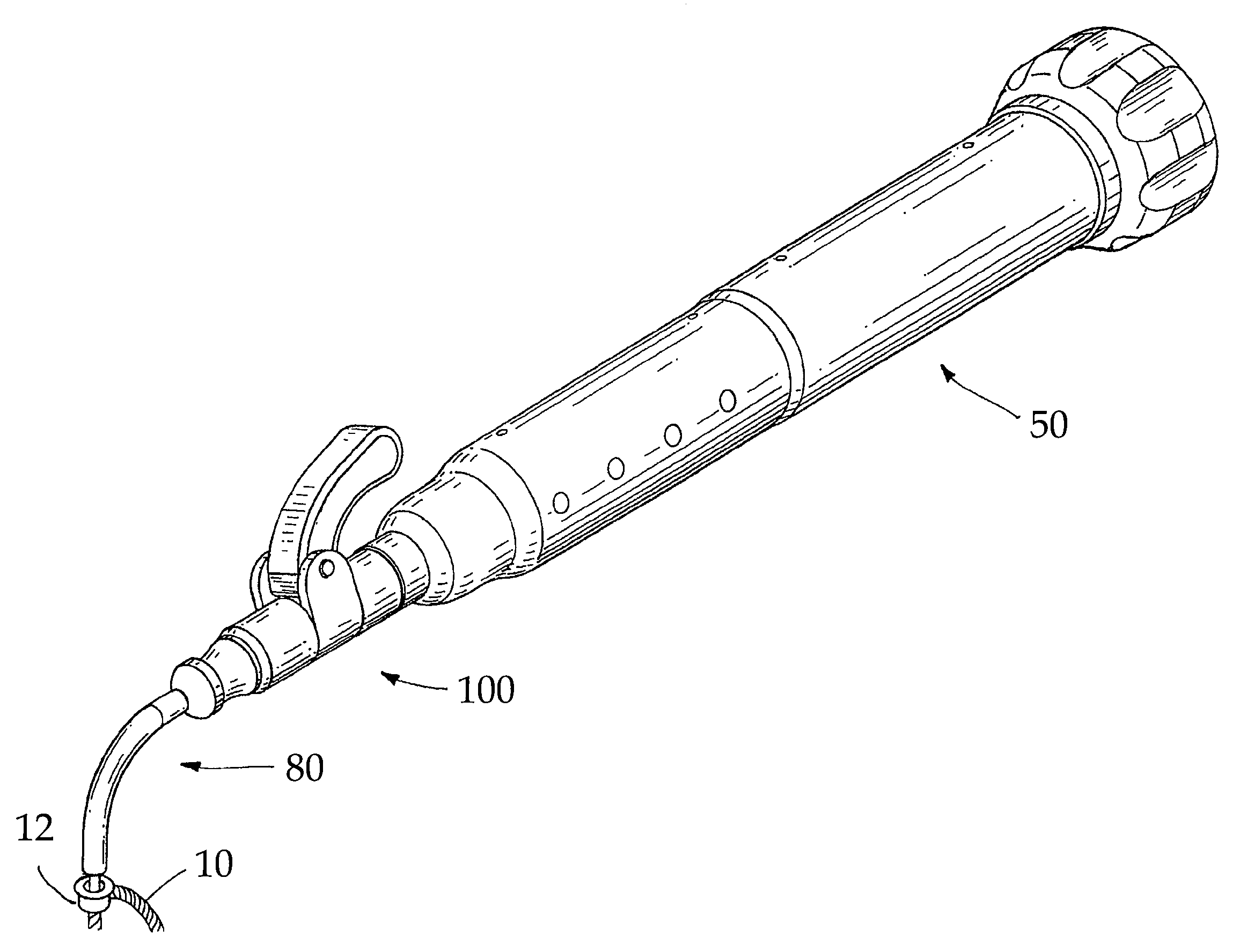
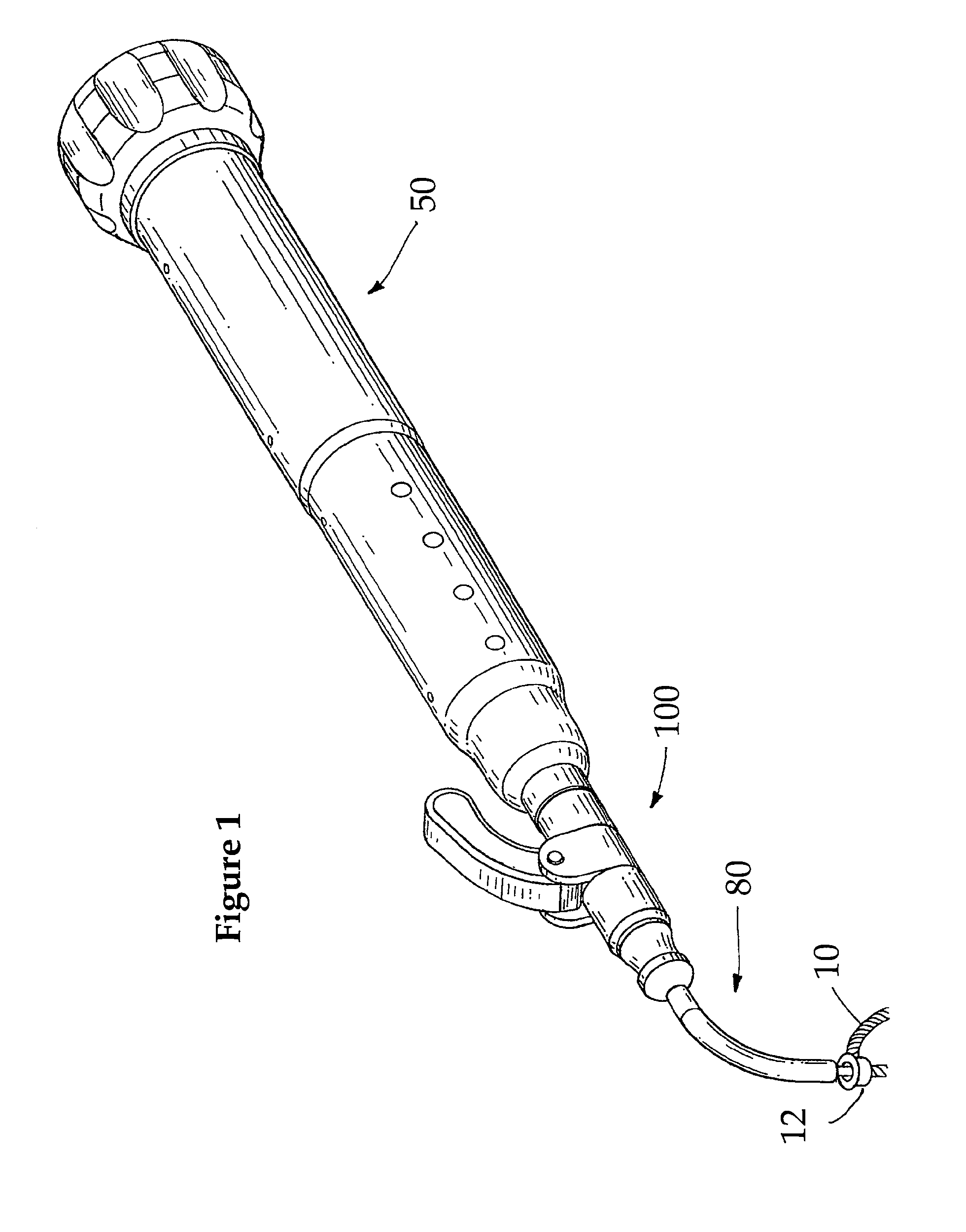
[0025]FIG. 1 illustrates an exemplary cable clamp 100 according to a preferred embodiment of the invention illustrated as part of a larger assembly that includes a tensioning tool 50 and a cable guide assembly 80. Although the invention will be described with reference to an exemplary cable clamp, it is not intended to be limited to devices for clamping cables, but is intended to encompass devices for clamping wires and other elongate members. Tensioning tool 50 provides a mechanism for applying a measured tension to cable 10, which extends through a “top hat” crimp 12 to form a loop for orthopedic fastening. As is known in the art, one end of the cable 10 is secured around the outside of the crimp and the other end extends through a bore in the crimp, through cable guide assembly 80, through a bore in cable clamp 100 and into the tensioning tool where it is gripped by a mechanism, the details of which are not important for an understanding of the invention.

[0026]Cable guide assembl...


PUM


Abstract

Disclosed is a clamp for securing cables or other elongate members used in surgical fastening procedures. The clamp advantageously applies a clamping force to the cable without direct contact with the cable, thereby reducing abrasion and shear forces applied to the cable. The disclosed clamps have a saddle member, platen or both that are movably mounted with respect to the housing and a lever, in cooperation with a cam surface, that allows the saddle member, platen or both to selectively clamp the cable. The lever may have several locking positions to provide optimum clamping force to different sized cables.

Description

[0001]This is a continuation-in-part application of U.S. patent application Ser. No. 09 / 442,293 filed Nov. 19, 1999, now U.S. Pat. No. 6,378,289 from which priority is claimed and which is incorporated herein by reference in its entirety.FIELD OF THE INVENTION[0002]The invention relates generally to surgical methods and apparatus for clamping cables or wires. More particularly, the invention relates to methods and apparatus for clamping cables, wires or other elongate members used in orthopedic surgical techniques.DESCRIPTION OF THE PRIOR ART[0003]Surgical cables and wires are now used extensively in orthopedic surgery for securing bones and bone fragments in place and for fastening surgical implements to bones. Typically, surgical cables are implanted using tensioning devices, which apply tension to a cable looped around the bone, and crimps that are deformed to clamp the cable loop in place.[0004]The prior art is typified by U.S. Pat. No. 5,395,374 to Miller et al, the entire writ...

Claims


Application Information

Patent Timeline
Patent Type & Authority Patents(United States)
IPC IPC(8): A61B17/56A61B17/58A61B17/88
CPCA61B17/8861A61B17/8869Y10T24/394
Inventor TRUDEAU, JEFFREY L.KILPELA, THOMAS S.JANOWSKI, BRIAN P.
Owner PIONEER SURGICAL TECH INC
Why Eureka
Try Eureka