
Magnetic random access memory with stacked toggle memory cells having oppositely-directed easy-axis biasing

a random access memory and toggle technology, applied in the field of magnetic random access memory, can solve the problem that selected cells cannot be inadvertently switched, and achieve the effect of reducing the write field and reducing power consumption

Active Publication Date: 2008-11-18
INTELLECTUAL VENTURES HOLDING 81 LLC
View PDF14 Cites 33 Cited by
  • Summary
  • Abstract
  • Description
  • Claims
  • Application Information

AI Technical Summary

Benefits of technology

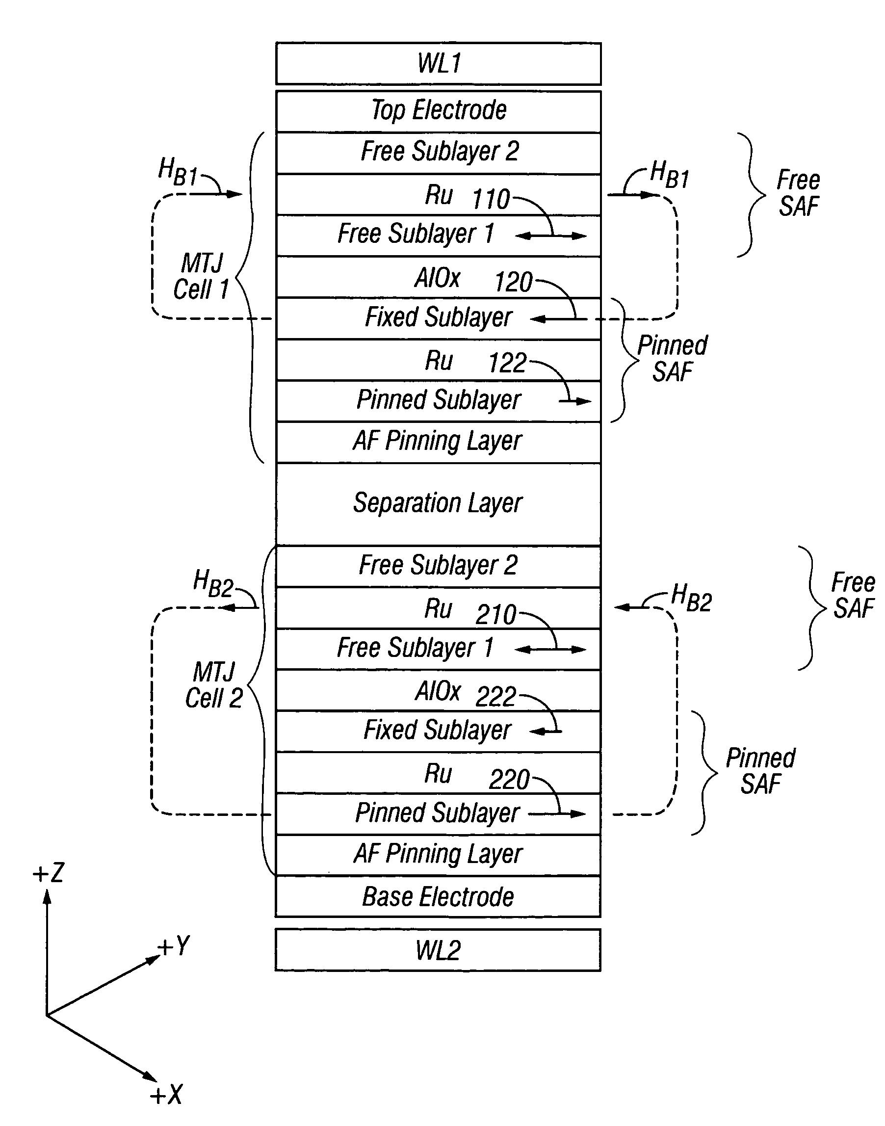
[0009]The invention is a toggling MRAM with memory stacks arranged in the X-Y plane on the MRAM substrate with each memory stack having a plurality of toggle memory cells stacked along the Z axis. Each stack is located at an intersection region between the two orthogonal write lines. The cells are stacked in pairs, with the cells in each pair having their easy axes of magnetization aligned substantially parallel to one another and nonparallel with the X and Y axes. The cells in each pair have their free layers biased in opposite directions. In one embodiment the biasing field is applied by the free layer's associated pinned layer, and in another embodiment by hard magnets located outside the stack. Because the free layer of each cell in a pair is biased in a direction opposite to the bias direction of the free layer of the other cell, one cell in a pair can be toggle written without toggle writing the other cell in the pair. Each cell in a pair is magnetically separated from the other cell in its pair by a nonmagnetic separation layer, and stacked pairs are also magnetically separated from one another by nonmagnetic separation layers. If there are N pairs in a stack (where N is 2 or more), the substantially parallel easy axes of magnetization of the free layers in the N pairs are generally equally angularly spaced about an axis parallel to the Z axis. Any cell in the stack can be toggle written without toggle writing any of the other cells in the stack. The bias field reduces the write field required to toggle switch a cell, thus resulting in a toggling MRAM with lower power consumption.

Problems solved by technology

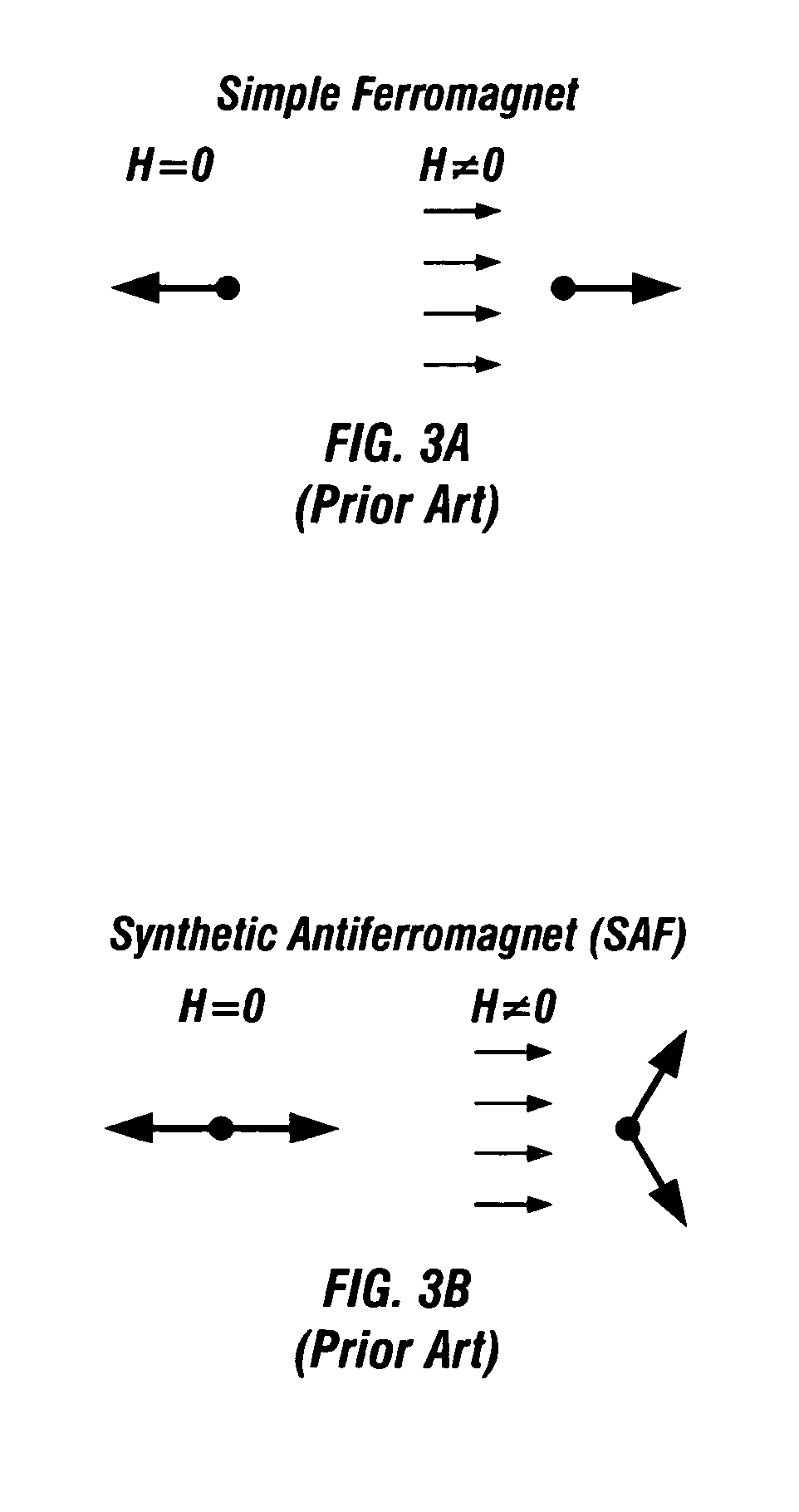
This single field is insufficient to switch the moments of the sublayers of the SAF free layers in the half-selected cells beyond their hard-axis instability points, so the magnetic states of the half-selected cells cannot be inadvertently switched when toggle writing to a selected cell.

Method used


Image

  • Magnetic random access memory with stacked toggle memory cells having oppositely-directed easy-axis biasing
  • Magnetic random access memory with stacked toggle memory cells having oppositely-directed easy-axis biasing
  • Magnetic random access memory with stacked toggle memory cells having oppositely-directed easy-axis biasing

Examples


Embodiment Construction

Prior Art

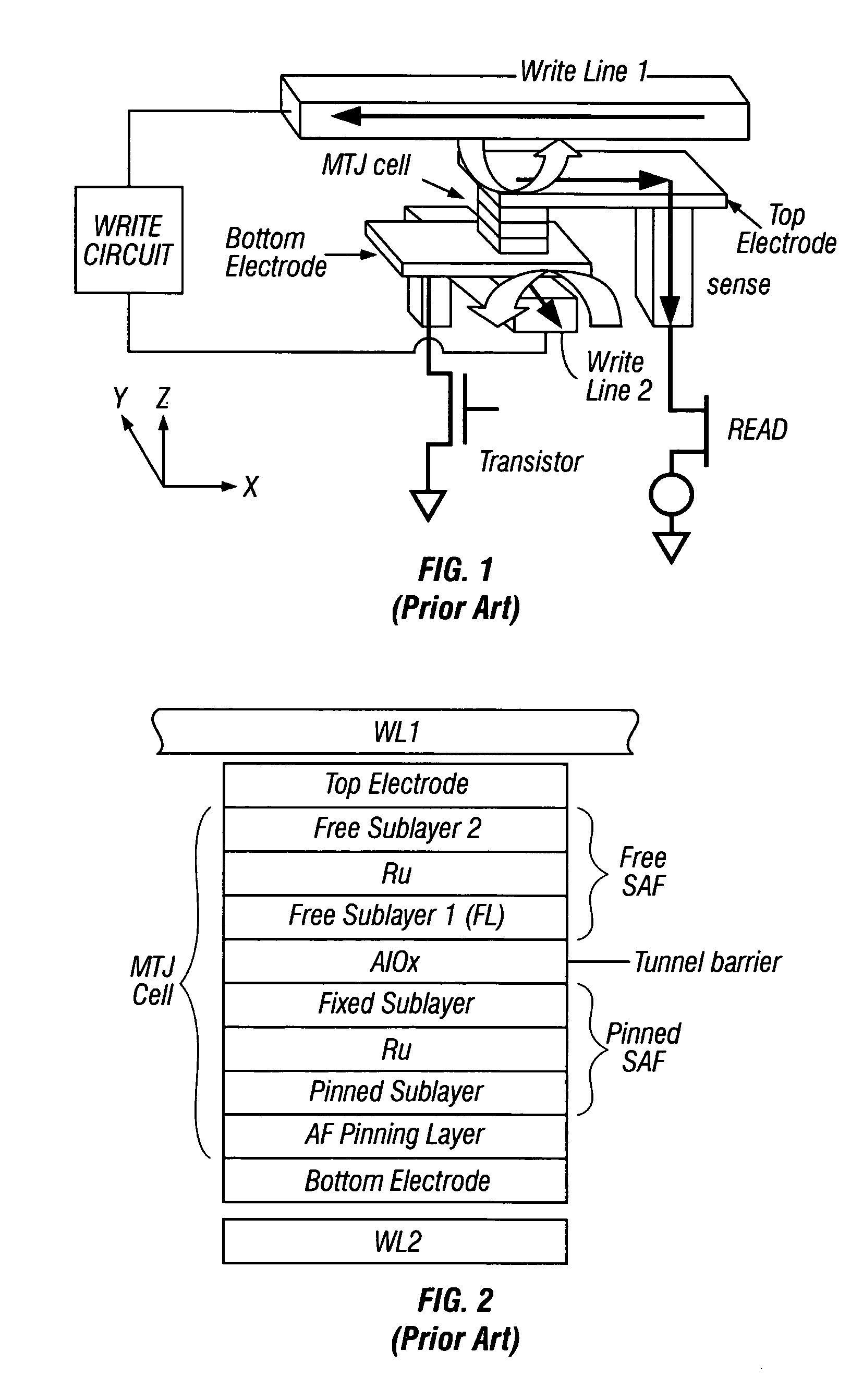
[0023]FIG. 1 is a perspective view of a portion of the prior art MRAM showing a single Savtchenko MTJ memory cell with a SAF free layer whose magnetization direction is switched by toggle writing. The MTJ cell is located in an intersection region between a second write line (WL2) (aligned along the Y axis) and a first write line (WL1) (aligned along the X axis). The write lines are connected to a write circuit that provides the sequence of current pulses to perform the toggle writing. Only one MTJ cell and intersection region is depicted in FIG. 1, but in the MRAM there are a plurality of generally parallel second write lines and a plurality of generally parallel first write lines that are orthogonal to the second write lines and overlap to define a plurality of intersection regions. Each intersection region contains an MTJ cell. Each MTJ cell is electrically connected to a transistor that is formed on the MRAM substrate (not shown). In the embodiment of FIG. 1 each MTJ cel...


PUM


Abstract

A “toggling” type of magnetic random access memory (MRAM) has memory stacks arranged in the X-Y plane on the MRAM substrate with each memory stack having a plurality of toggle memory cells stacked along the Z axis. Each stack is located at an intersection region between the two orthogonal write lines. The cells are stacked in pairs, with the cells in each pair having their easy axes of magnetization aligned substantially parallel to one another and nonparallel with the X and Y axes. The cells in each pair have their free layers magnetically biased in opposite directions. Because the free layer of each cell in a pair is biased in a direction opposite to the bias direction of the free layer of the other cell, one cell in a pair can be toggle written without toggle writing the other cell in the pair. The bias fields on the free layers reduces the required switching field for each cell, which results in less write current and a lower-power toggling MRAM.

Description

BACKGROUND OF THE INVENTION[0001]1. Field of the Invention[0002]This invention relates generally to magnetic random access memory (MRAM) and more particularly to MRAM with “toggle” memory cells.[0003]2. Description of the Related Art[0004]MRAM with magnetic tunnel junction (MTJ) memory cells has been proposed for nonvolatile memory, as described in U.S. Pat. No. 5,640,343 and by Reohr et al., “Memories of Tomorrow”, IEEE CIRCUITS & DEVICES MAGAZINE, September 2002, pp. 17-27. In these devices the MTJs are arranged as an array in a single layer (the X-Y plane) on a semiconductor substrate. In one type of architecture, called a 1T1MTJ MRAM (one transistor and one MTJ), each MTJ is located between a bit line and a transistor, with the word lines located beneath the MTJs. In another type of architecture, called a cross-point (XPC) MRAM, the MTJs are located directly between the bit and word lines.[0005]In both MRAM architectures, a selected MTJ cell is programmed or “written”, i.e., its...

Claims


Application Information

Patent Timeline
Patent Type & Authority Patents(United States)
IPC IPC(8): G11C11/02
CPCG11C11/15G11C11/5607H01L27/222H01L27/228H10B61/00H10B61/22
Inventor JU, KOCHANCHANG, JEI-WEI
Owner INTELLECTUAL VENTURES HOLDING 81 LLC
Learn More