
Direct print system

a printing system and printing technology, applied in the direction of digital output to print units, sensing record carriers, instruments, etc., can solve the problems of image data not being transmitted to a specific printer, encrypted communication cannot be performed,

Active Publication Date: 2008-11-25
FUJIFILM CORP
View PDF18 Cites 31 Cited by
  • Summary
  • Abstract
  • Description
  • Claims
  • Application Information

AI Technical Summary

Benefits of technology

The present invention provides a direct print system that allows for easy printing using wireless-LAN information. The system includes a printer, a digital camera, and a wireless-LAN information acquisition device. The printer has a wireless-LAN information acquisition device that can acquire wireless-LAN information, including setting information and transmission-destination information. The wireless-LAN information acquisition device generates a bar code representing the wireless-LAN information, which is then outputted by the printer. The digital camera senses the bar code and outputs data representing the bar code. The wireless-LAN information is transmitted to the printer using the setting information and transmission-destination information. The system simplifies printing by using wireless-LAN information.

Problems solved by technology

However, encrypted communication cannot be performed unless information such as WEP-KEY is set in order to construct a direct print system utilizing wireless communication.
Further, in a case where printers are connected on a network and a large number of devices have been connected on this network, image data cannot be transmitted to a specific printer unless the destination of the transmission is specified.

Method used


Image

  • Direct print system
  • Direct print system
  • Direct print system

Examples


Embodiment Construction

[0036]A preferred embodiment of the present invention will now be described in detail with reference to the drawings.

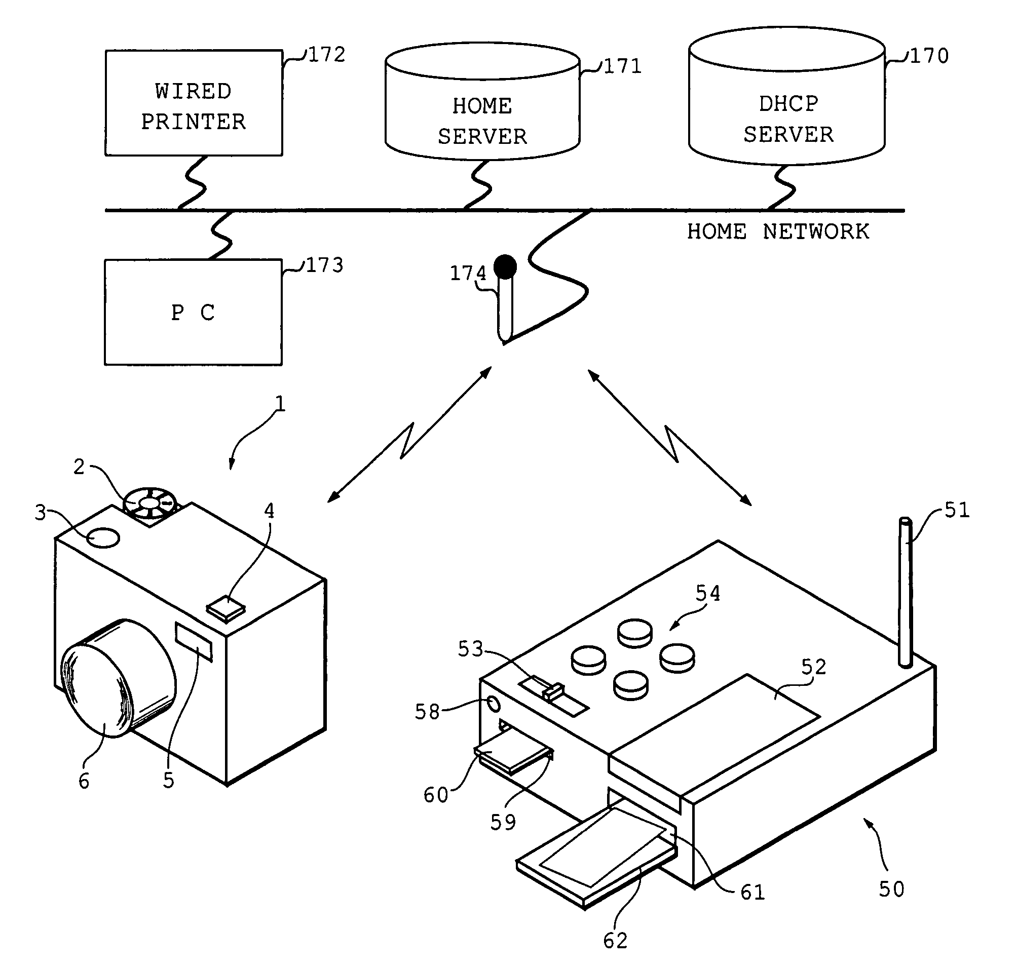
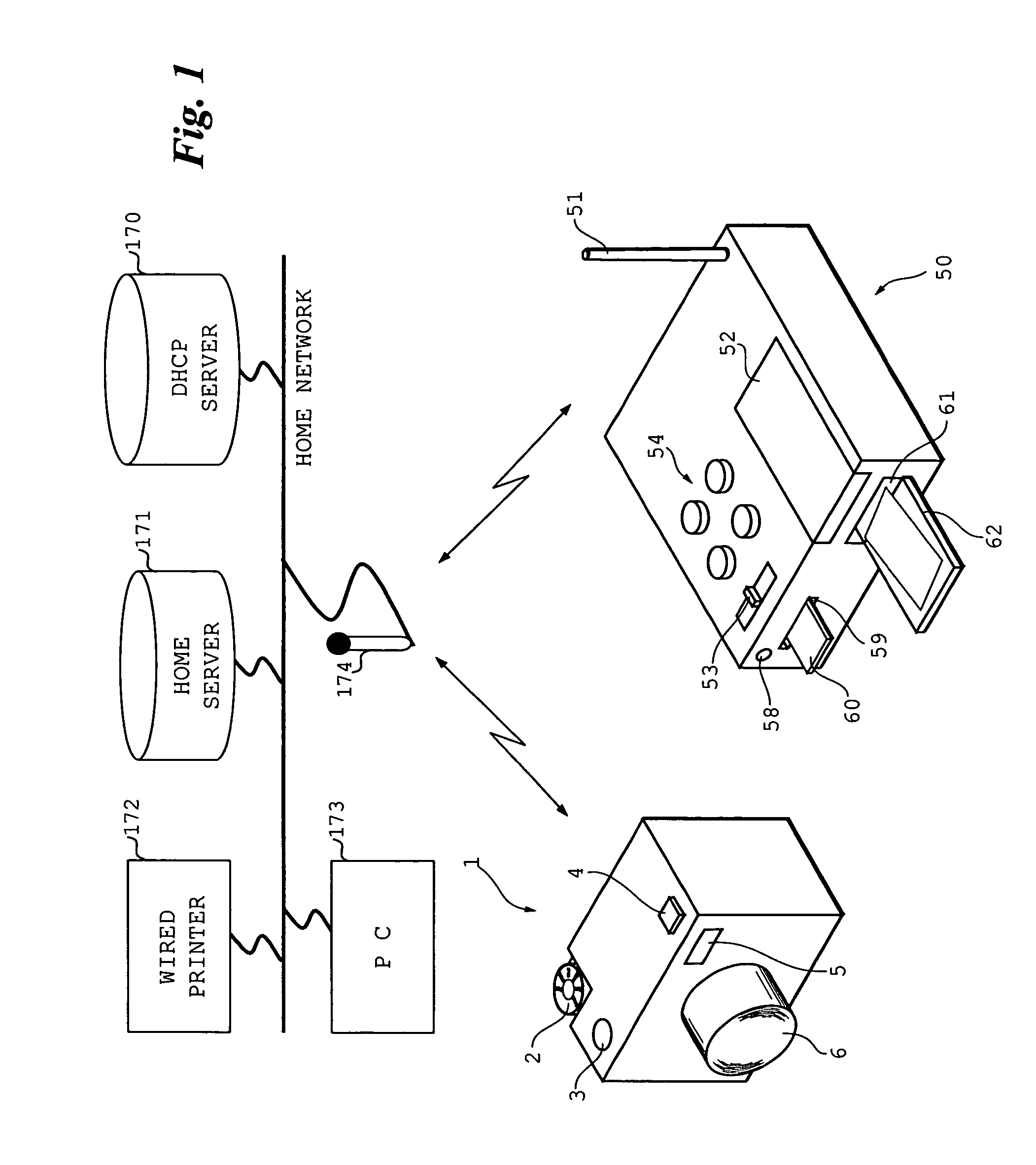
[0037]FIG. 1 illustrates a direct print system that utilizes a home network in an embodiment of the present invention.

[0038]Connected to the home network is an access point unit 174 via which a digital still camera 1 and a printer 50 (which construct a direct print system) are capable of communicating with each other (in an infrastructure mode).

[0039]Also connected to the home network in addition to the access point unit 174 are a DHCP (Dynamic Host Configuration Protocol) server (server) 170, a home server 171, a wired printer (this printer is referred to as a “wired printer” to distinguish it from the printer 50, which constructs the direct print system) 172, and a personal computer 173.

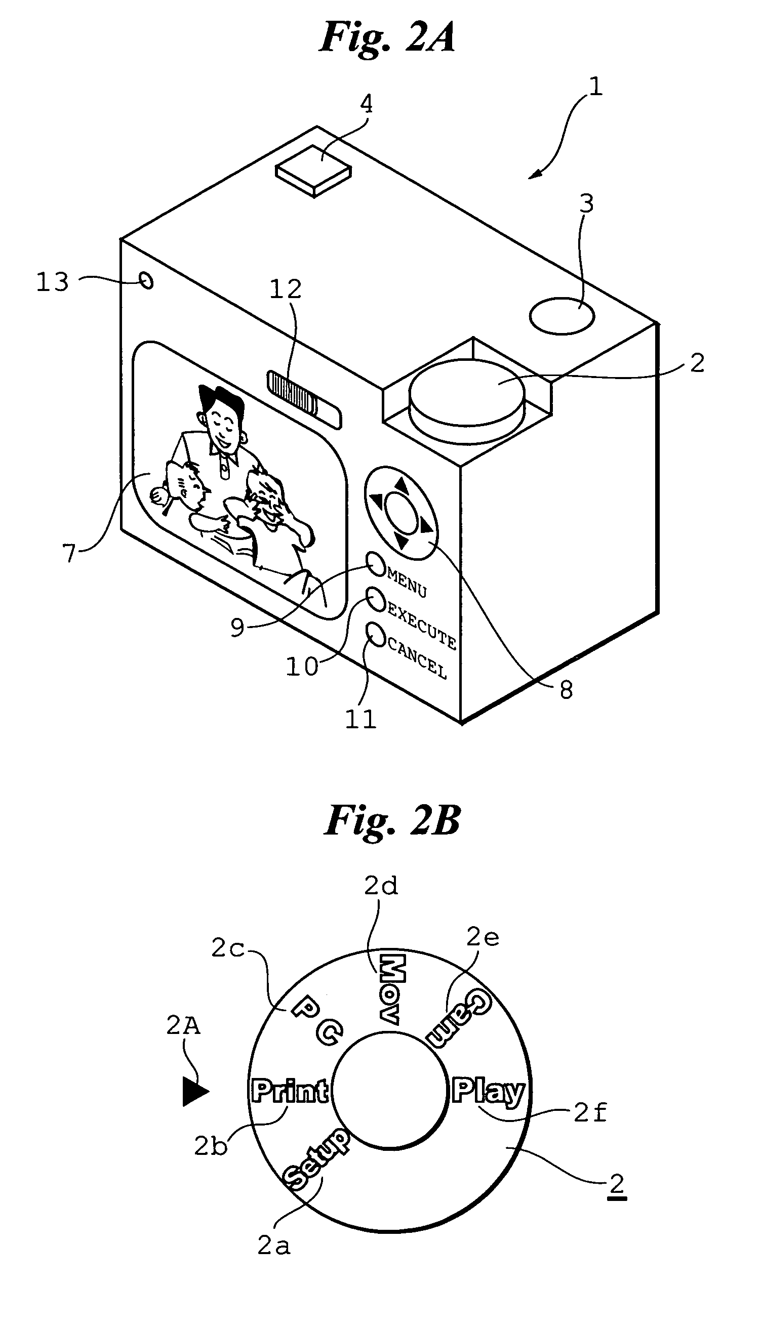
[0040]Provided on the top of the digital still camera 1 on the left side thereof are a mode selection dial 2 and shutter-release button 3. A radio communication antenna 4 is provided...


PUM


Abstract

Wireless-LAN information is set in a digital still camera in a comparatively simple manner. Specifically, if a digital still camera and a printer are to communicate utilizing a wireless LAN, the printer generates a two-dimensional bar code containing wireless-LAN setting information such as ESS-ID and WEP KEY, and printer setting information such as an IP address. The printer is used to generate a direct print setting sheet on which have been recorded the generated two-dimensional bar code as well as the wireless-LAN setting information and printer setting information. The digital still camera is used to take a picture of the two-dimensional bar code and read the wireless-LAN setting information and printer setting information from the two-dimensional bar code. The read wireless-LAN setting information and printer setting information is set in the digital still camera, and the printer and digital still camera cooperate to perform direct printing using the wireless LAN.

Description

BACKGROUND OF THE INVENTION[0001]1. Field of the Invention[0002]This invention relates to a direct print system, a printer and a digital camera (inclusive of a portable information device having the function of a digital still camera, an example of which is a mobile telephone equipped with a camera) that construct this system, and methods of controlling the printer and digital camera.[0003]2. Description of the Related Art[0004]When an image is printed, a printer is connected to a personal computer and image data is transmitted from the personal computer to the printer. The image represented by the image data is printed by the printer. The general practice is to connect the personal computer and the printer when an image is to be printed. If an image that has been captured by a digital camera is printed, image data representing the image is stored once in the personal computer.[0005]In recent years, however, it has become possible to connect a digital still camera and a printer dire...

Claims


Application Information

Patent Timeline
Patent Type & Authority Patents(United States)
IPC IPC(8): G06K7/10H04K1/00H04N1/00
CPCH04N1/00278H04N1/00363H04N1/00371H04N1/00968H04N2201/0039H04N2201/0055H04N2201/0084G06F3/12
Inventor TANAKA, HIROSHI
Owner FUJIFILM CORP
Learn More