Backlight module using replaceable external electrode lamps

a technology of backlight module and external electrode, which is applied in the field of backlight modules, can solve the problems of high failure rate during operation, complicated welding or copper belting process, and high failure rate of the device, and achieves the effects of easy replacement, strong shock resistance and impact resistance, and increased safety and reliability of the produ

Inactive Publication Date: 2008-11-25
HANNSTAR DISPLAY CORPORATION
View PDF3 Cites 0 Cited by
  • Summary
  • Abstract
  • Description
  • Claims
  • Application Information

AI Technical Summary

Benefits of technology

[0015]The present invention offers the advantage of allowing the lamps of the backlight module to be easily replaced through its unique structure. This is accomplished through removing the externally replaceable light source set, changing the lamps on replaceable the light source set, and pushing back the replaceable light source set to complete the lamp replacement. The structure also provides distinctive features including an optimized electrode cladding and a strong resistance to shocks and impacts to thereby increase the safety and reliability of the product.

Problems solved by technology

The welding or copper belting processes however, are both rather complicated and may result in high failure rates during operation.
For example, poor soldering can often cause a fake welding effect.
Fake welding effects are particularly susceptible to melting or breakage upon the lighting of the electrode, as sufficient heat is generated that will result in temperatures high enough to melt solder and damage the area of the fake weld.
Also, if excess solder is located between the conducting end and the conducting wire, an electric discharge can result that can cause scorching or electrical leakage.
This problem is typically addressed through the addition of an insulated heat-shrink tube to cover the external area of the copper belt, resulting in additional manufacturing costs for the CCFL.
Although this patent design essentially manages to solve the aforementioned problems, the luminosity and life expectancy of the lamp proves more and more inefficient as backlight lamp technologies advance, and LCD panel sizes continue to increase.
Because the electrodes of EEFLs are constantly driven by high voltages while being exposed to external environments, numerous electric shocks are commonly experienced.
In addition, the layout of the electrode power supply used to stabilize the external electrode lamp places various limitations on the shock resistance design.
Consequently, many of the EEFL products sold in the market today still suffer from problems such as poor electrode cladding and poor shock resistance.
If any single lamp becomes damaged or broken, the overall illumination decreases, resulting in a poor display quality.
The replacement of damaged lamps is therefore a tedious and precise process that introduces the possibility of damaging other components during repair.
In particular, other components such as adjacent lamps, optical film sets, and the driver circuit are very fragile, and are easily susceptible to damage when replacing a damaged lamp.
As LCDs become larger and larger, the effort required to replace lamps in an LCD becomes increasingly larger and more difficult.

Method used


Image

  • Backlight module using replaceable external electrode lamps
  • Backlight module using replaceable external electrode lamps
  • Backlight module using replaceable external electrode lamps

Examples


Embodiment Construction

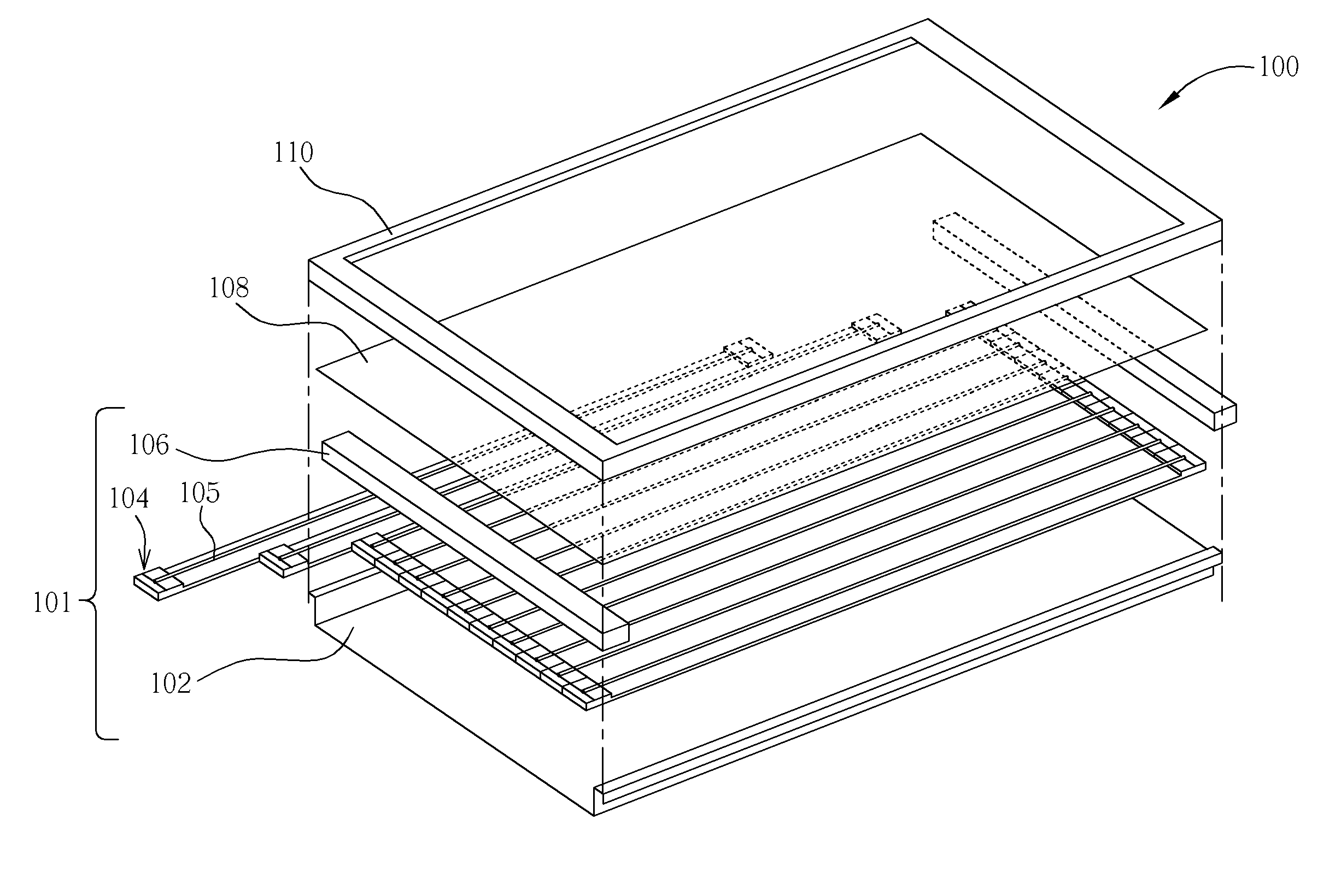
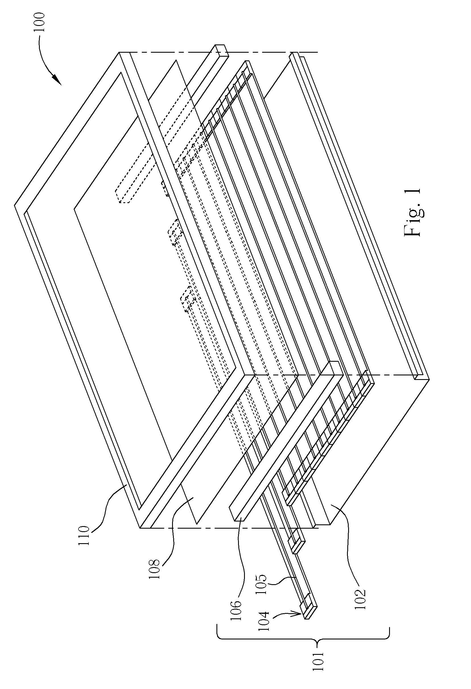
[0025]FIG. 1 illustrates a magnified view of an LCD comprising a backlight module according to the present invention. The LCD 100 includes a backlight module 101, an optical film set (not shown), an LCD panel 108, and a bezel 110. The backlight module 101 includes a back plate 102, a plurality of replaceable light source sets 104, a plurality of external electrode lamps 105, and a fastening device 106. The LCD panel 108 is disposed on the fastening device 106. The distinct features of LCD will be described later in more detail.

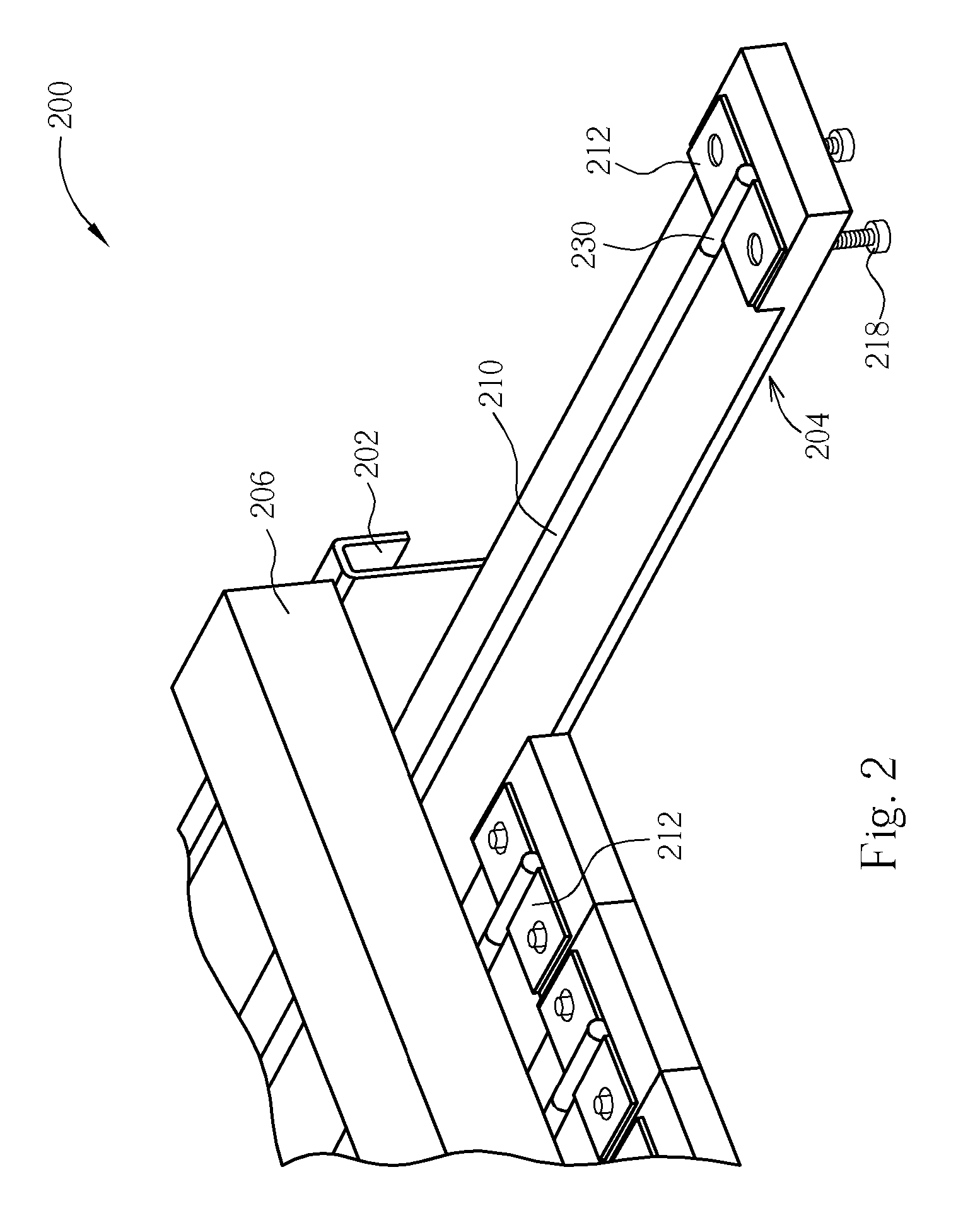
[0026]FIGS. 2 and 3 show various views of a backlight module according to an embodiment of the present invention. As shown in FIGS. 2 and 3, the backlight module 200 includes a back plate 202, a plurality of replaceable light source sets 204, a plurality of external electrode lamps 210, and a fastening device 206. The back plate 202 includes a plurality of first track sets 208 disposed on a surface thereof. The replaceable light source sets 204 are disposed on...


PUM


Abstract

A backlight module includes a back plate, replaceable light source sets, external electrode lamps, and a fastening device. Each replaceable light source set is disposed on the back plate and has an electrically conductive strip. The external electrode lamps are disposed on one of the replaceable light source sets and each has an external electrode electrically connected with the electrically conductive strip. The fastening device is used for fastening the replaceable light source sets and comprises an electrically conductive element electrically connected with the electrically conductive strips.

Description

CROSS REFERENCE TO RELATED APPLICATIONS[0001]This is a continuation-in-part of U.S. application Ser. No. 10 / 711,257, which was filed on Sep. 5, 2004 and is included herein by reference.BACKGROUND OF THE INVENTION[0002]1. Field of the Invention[0003]The invention relates to backlight modules, more particularly to a backlight module using replaceable external electrode lamps.[0004]2. Description of the Prior Art[0005]Most TFT-LCD (thin film transistor liquid crystal display) displays today utilize cold cathode fluorescent lamps (CCFL) for their backlight modules, where the electrodes of the lamps are effectively sealed inside. The electrode contains a conducting end that extends from the internal electrode to an external conducting wire. The conducting wire then connects to a power supply in order to draw energy for the lamp.[0006]The conducting end of the CCFL is typically connected to the conducting wire through either a welding or a copper belting process. The welding or copper bel...

Claims


Application Information

Patent Timeline
Patent Type & Authority Patents(United States)
IPC IPC(8): F21V7/04
CPCH01J61/0672H01J61/305H01J65/046G02F1/133604
Inventor HUANG, CHI-JENLAI, HSIN CHIEH
Owner HANNSTAR DISPLAY CORPORATION
Why Eureka
Try Eureka