

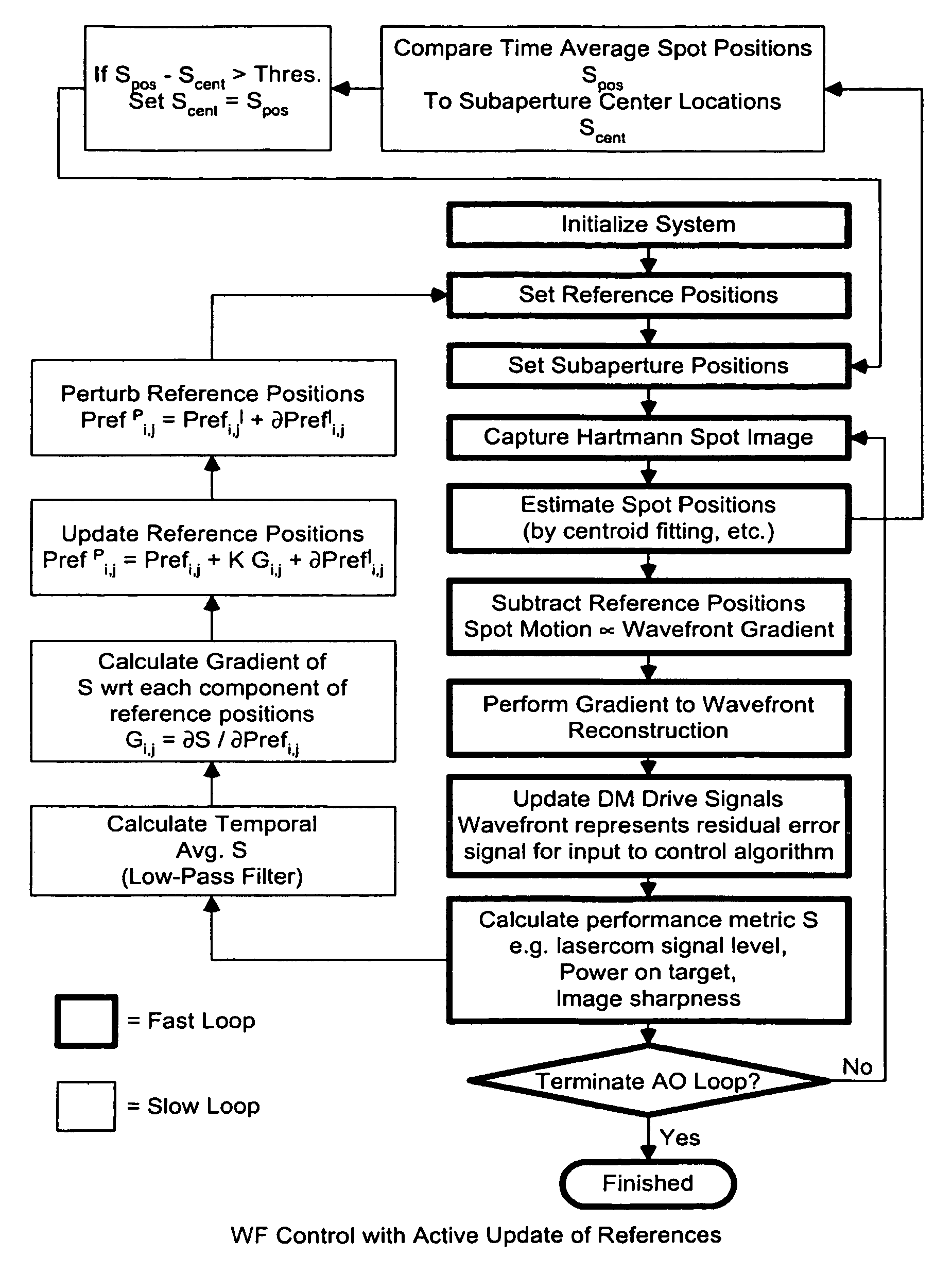
Process for controlling a Hartmann wavefront sensor (WFS) in an adaptive optic (AO) system
a technology of adaptive optics and sensors, applied in the field of bidirectional laser communication links, can solve the problems of single dm, inability to correct both phase and intensity in the beam, and possible significant signal fade events, so as to improve the condition of the laser beam, automatically stabilize the intensity of received variations, and reduce the size of the spot
- Summary
- Abstract
- Description
- Claims
- Application Information
AI Technical Summary
Benefits of technology
Problems solved by technology
Method used
Image

Examples
Embodiment Construction
[0136]Referring to the figures in the accompanying Drawings, the various illustrative embodiments of the methods, systems and devices (i.e. instruments) of the present invention will be described in great detail, wherein like elements will be indicated using like reference numerals.
General Description of Laser Communications Link Fade Prevention Techniques of the Present Invention
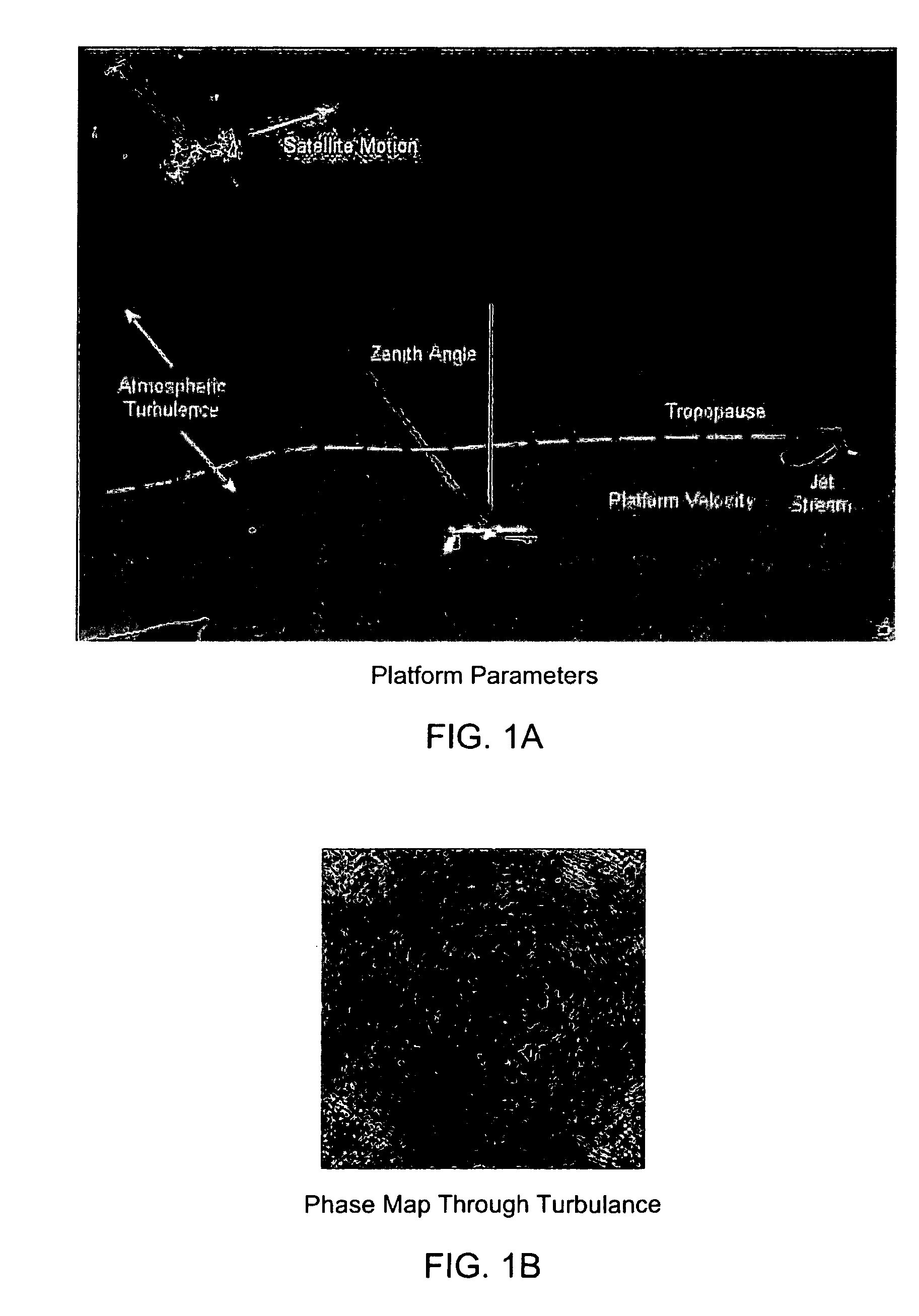
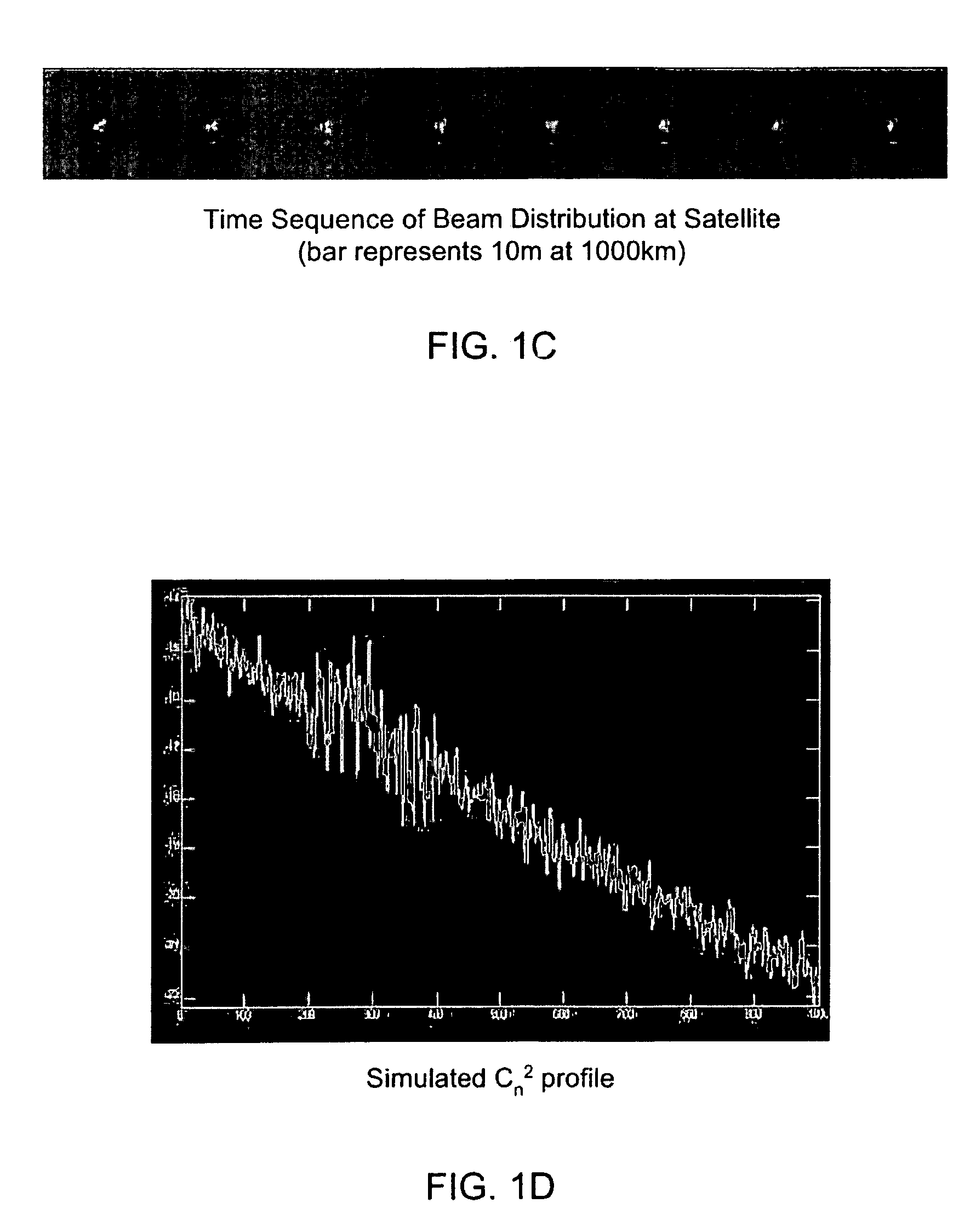
[0137]Through research, Applicants have discovered that the spatial intensity variations in the received laser beam signal at the input plane of a receiver lead to temporal fluctuations in the total power received. FIG. 1K shows a simulation of a typical intensity distribution at the plane of the receiver aperture. This case is for a 10 km path through an atmosphere with Cn2=1.0×10⁻¹⁴ m−2.3. The transmitter and receiver apertures are both 20 cm in diameter and the wavelength is 1.5 microns. The full image shown is 1 m×1 m. This intensity pattern varies randomly as the turbulence along the path changes.
[0138...
PUM
 Abstract
Description
Claims
Application Information