Graphical interface for configuring a power supply controller

a technology for power supply controllers and graphical interfaces, applied in the direction of process and machine control, digital computer details, instruments, etc., can solve the problem of relatively complex configuration information of the controllers

Inactive Publication Date: 2008-11-25
POWER INTEGRATIONS INC
View PDF39 Cites 7 Cited by
  • Summary
  • Abstract
  • Description
  • Claims
  • Application Information

AI Technical Summary

Problems solved by technology

While such a power supply controller is very versatile, it can be seen that its configuration information is relatively complex.

Method used


Image

  • Graphical interface for configuring a power supply controller
  • Graphical interface for configuring a power supply controller
  • Graphical interface for configuring a power supply controller

Examples


Embodiment Construction

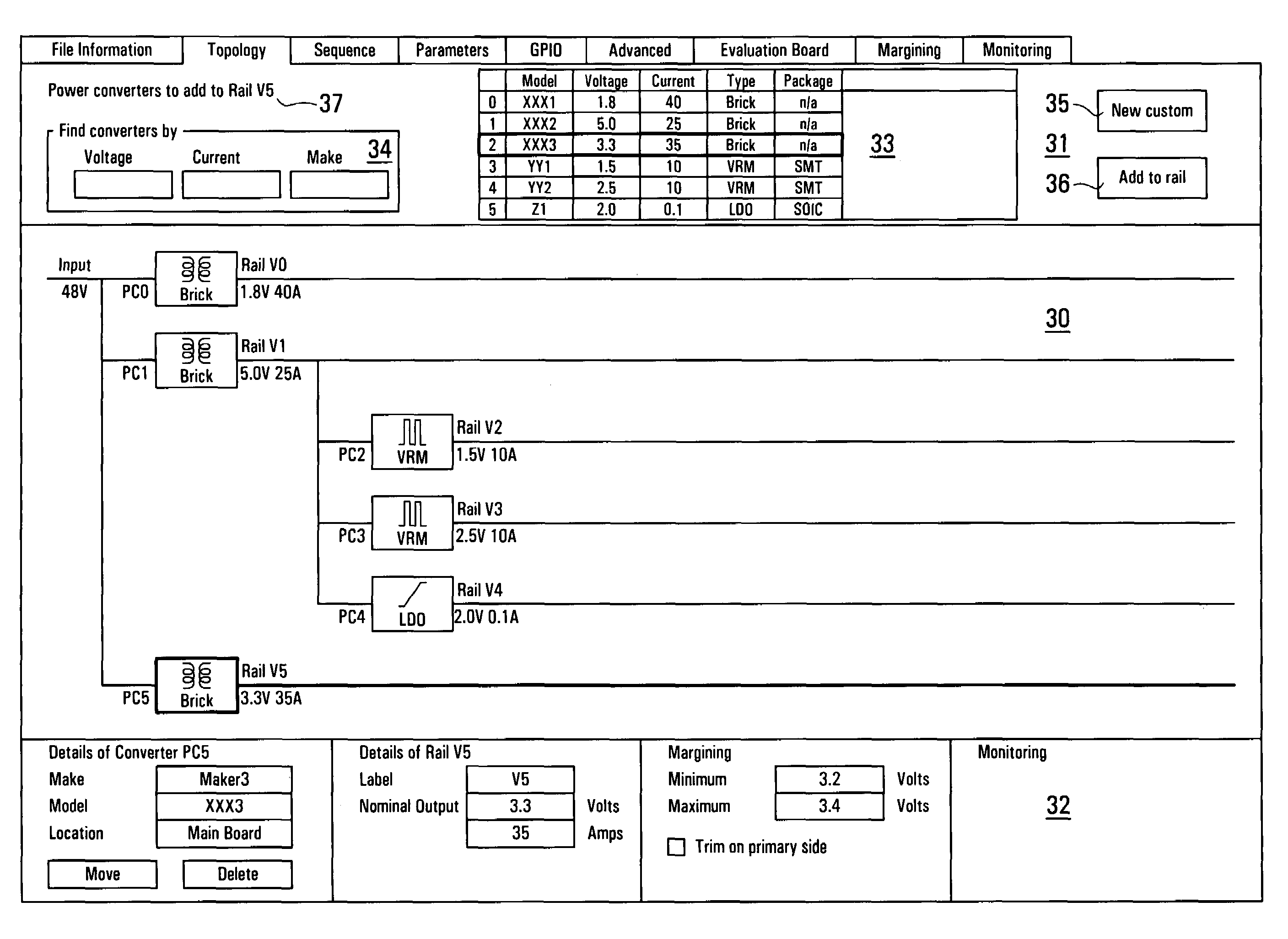
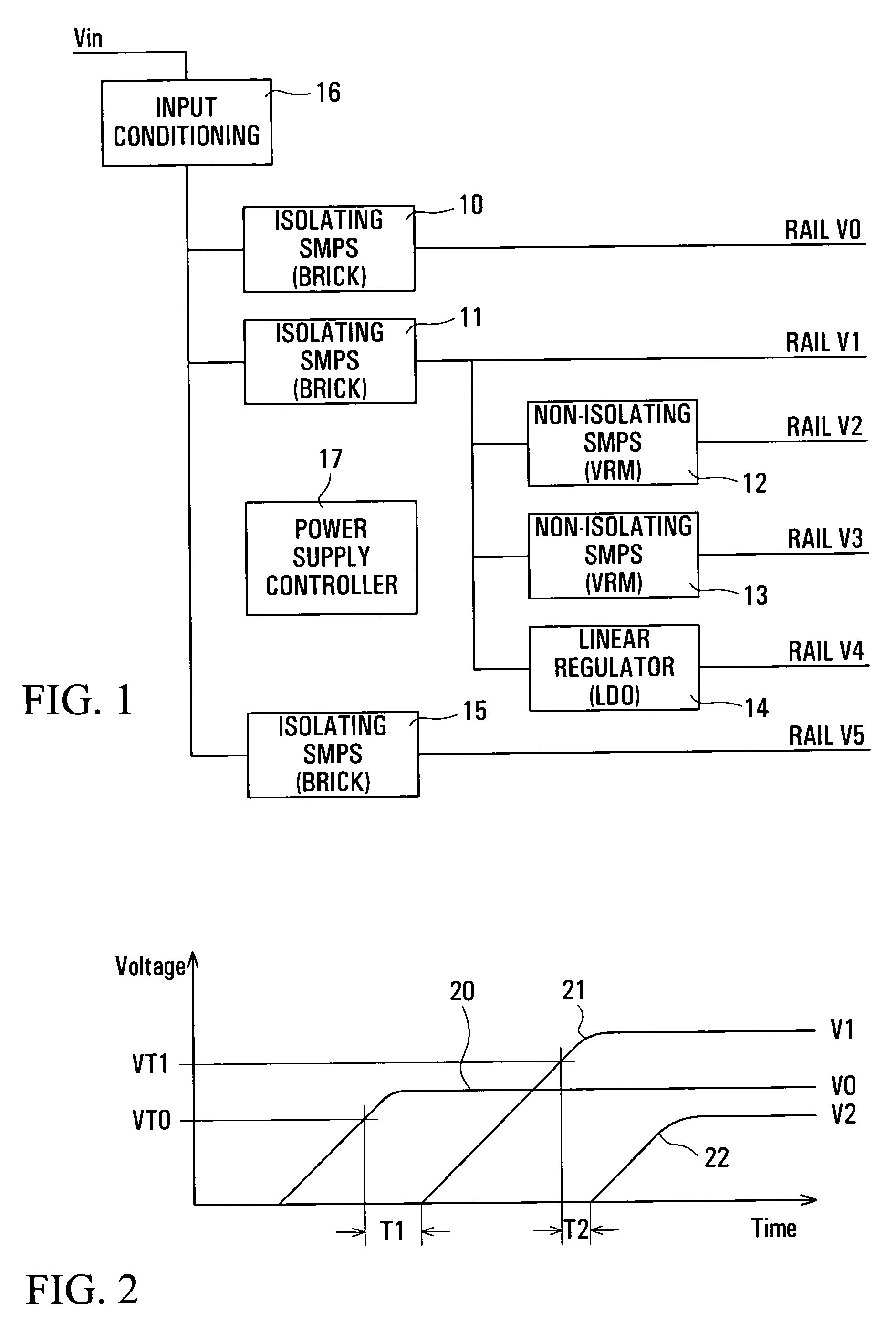
[0034]Referring to FIG. 1, a power system is illustrated by way of example as including six power supplies or converters 10 to 15, an input voltage conditioning unit 16, and a power supply controller 17, all of which for example may be provided on a circuit card which, when inserted in an electrical equipment slot, is connected to an input power supply voltage Vin of for example 48 volts which serves as a power source for the entire card. The controller 17 then controls the power supplies 10 to 15 for producing respective supply voltages on rails V0 to V5 for electrical circuits on the circuit card. This control includes monitoring of the input voltage Vin and the output voltages of the controlled power supplies 10 to 15, and sequencing of the power supplies on power-up, normal shut-down, and fault shut-down, for example as described in the related patent applications referred to above.

[0035]A power system can have any number of controlled power supplies or converters, and these can...


PUM


Abstract

Information for configuring control apparatus for a power system including a plurality of controlled power supplies is produced using a graphical interface which displays the topology and sequencing of the power supplies in the power system. A database is used to select power supplies to add in determining the power system topology. Sequencing is represented by displacing icons representing the power supplies along lines representing their input and output voltages, and arrows representing startup sequence dependencies. A processor produces the configuration information, consistent with the displayed topology and sequencing, using information for the selected power supplies from the database, for downloading to the control apparatus.

Description

[0001]This invention relates to a graphical interface for use in configuring a power supply controller, in particular a power supply controller that can be used for controlling a plurality of power supplies. The term “power supply” is used herein to refer to any type of device for supplying controlled electrical power for a load. For example, the power supplies may comprise isolating and / or non-isolating switch mode power supplies or DC power converters, voltage regulator modules, and linear voltage regulators.REFERENCE TO RELATED APPLICATIONS[0002]Reference is directed to the following copending United States patent applications, the entire disclosure of each of which is hereby incorporated herein by reference:[0003]“Power Supply Controller”, R. Orr et al., application Ser. No. 10 / 428,095 filed May 2, 2003;[0004]“Sequencing Power Supplies”, D. Brown et al., application Ser. No. 10 / 428,105 filed May 2, 2003;[0005]“Sequencing Power Supplies On Daughter Boards”, D. Brown et al., appli...

Claims


Application Information

Patent Timeline
Patent Type & Authority Patents(United States)
IPC IPC(8): G06F15/177G06F15/18G05F1/40H02J1/00H02J3/00H02J13/00
CPCH02J13/001Y04S10/40H02J13/00001
Inventor CHIDAMBARAM, AVINASHPENN, RICHARD FRANCISCOOPER, DAVID
Owner POWER INTEGRATIONS INC
Why Eureka
Try Eureka