Protective cover

a protective cover and cover technology, applied in the field of protective covers, can solve the problems of complicated structure operation and considerable inconvenient handling, and achieve the effect of convenient opening and closing

Active Publication Date: 2008-12-02
DENYO LMTD
View PDF9 Cites 2 Cited by
  • Summary
  • Abstract
  • Description
  • Claims
  • Application Information

AI Technical Summary

Benefits of technology

[0012]The present invention is made in view of the above points, and has its object to provide a protective cover capable of enhancing convenience in connecting and disconnecting external output lines and the like without impairing safety.
[0018]Since in the present invention, the protective cover of the double lid structure with the outer lid and the internal lid is adopted as described above, and therefore, the protective cover, in which the outer lid can be easily opened and closed by the operation of an operation lever and when the outer lid is opened, a preliminary protective state by the internal lid is achieved, can be provided.

Problems solved by technology

However, when the external output lines are frequently connected and disconnected, these structures require complicated operations and are considerably inconvenient in handling.

Method used


Image

  • Protective cover
  • Protective cover
  • Protective cover

Examples


Embodiment Construction

[0031]Hereinafter, an embodiment of the present invention will be explained with reference to FIGS. 1 to 9.

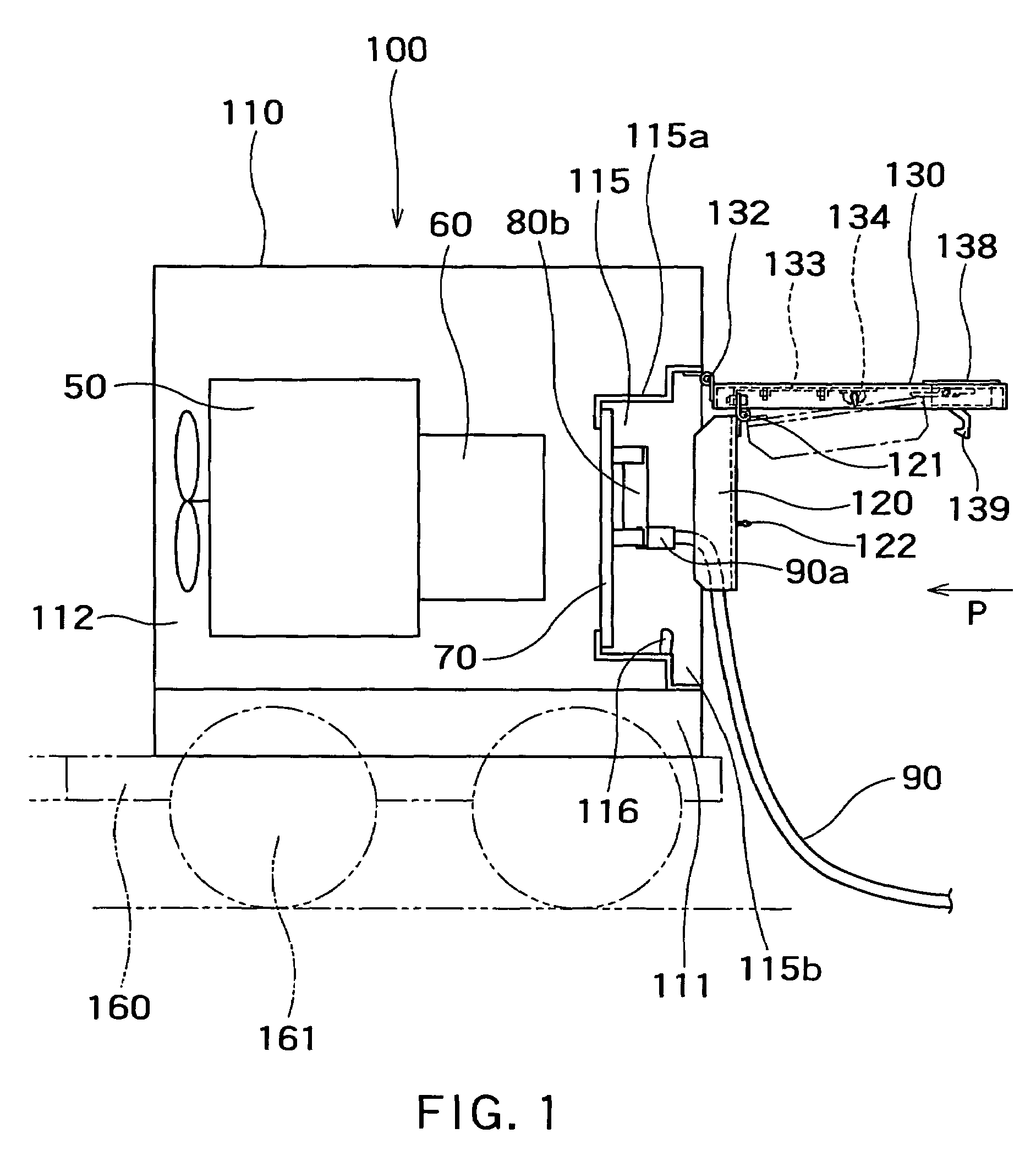
[0032]FIG. 1 is a side view of a first embodiment of the present invention. In FIG. 1, an example as a protective cover provided at an output terminal part of a portable engine driven generator 100 is shown.

[0033]The engine driven generator 100 has an engine 50 and a generator 60 directly connected, and is housed in a casing 110. The casing 110 is constructed by placing a housing chamber 112 on a base 111, and the output terminal part is provided at a right side in the drawing, of the housing chamber 112. The base 111 is loaded on a carriage 160, and is movable by a wheel 161.

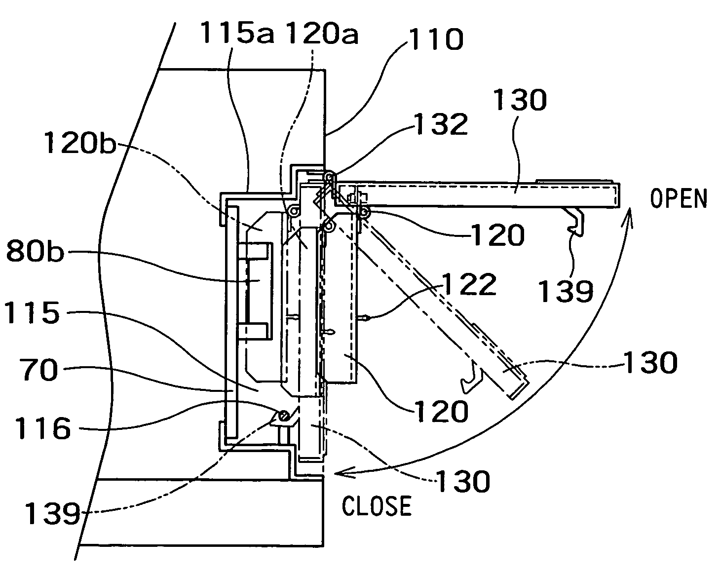
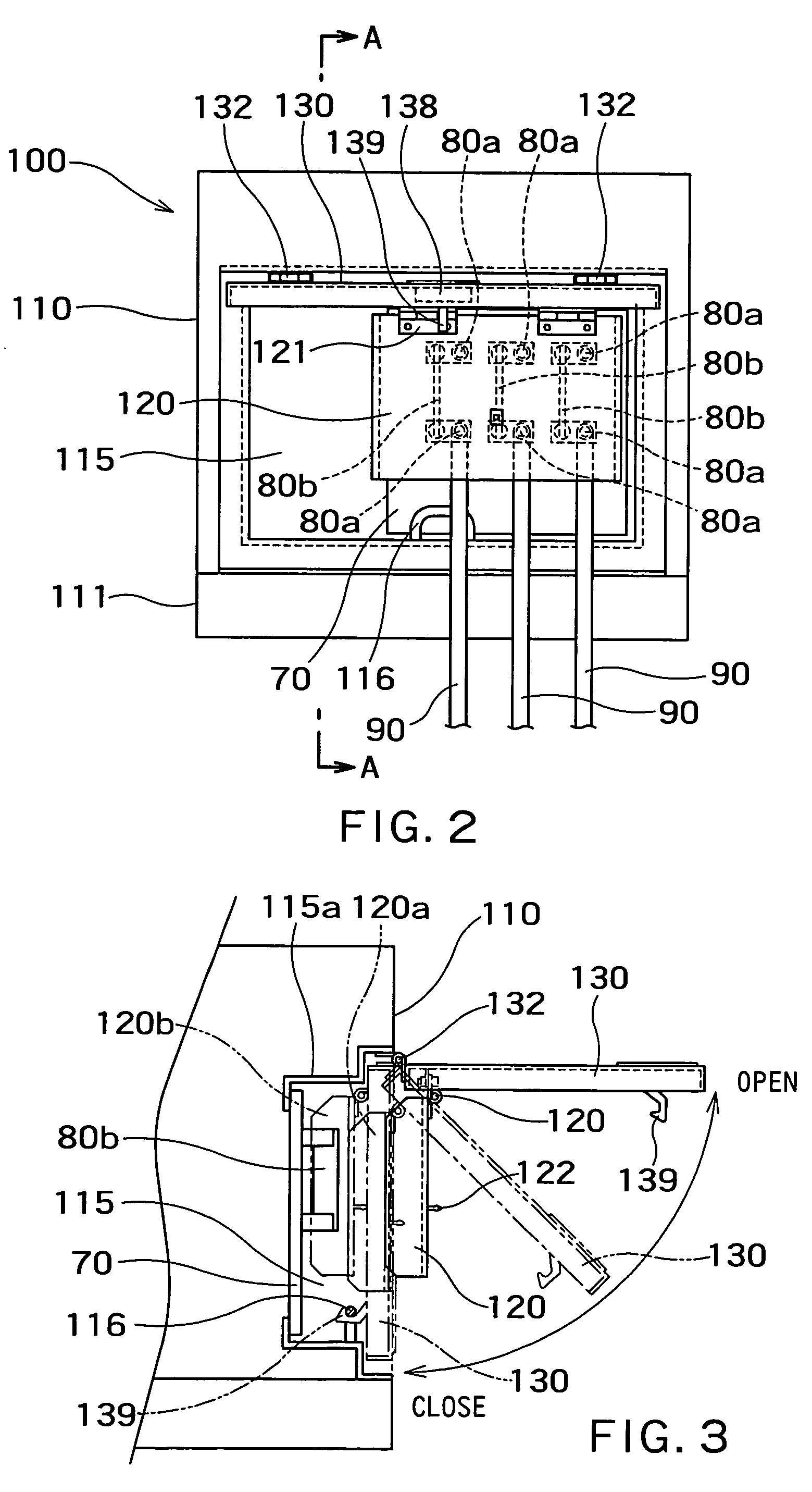
[0034]The output terminal part is formed as a box-shaped space inside a mounting frame 115a. An output terminal is placed in this box-shape space, and a front surface is covered with an outer lid 130 of a protective cover.

[0035]In the box-shaped space, a blade type terminal plate 80b and a plug-in terminal...


PUM


Abstract

To provide a protective cover capable of enhancing convenience in connecting and disconnecting an external output line and the like without impairing safety. In a protective cover placed on a side wall of a casing and covering a hollow part in which an output part of an apparatus housed in the casing is provided, the cover is characterized by including an outer lid which is supported by a hinge provided at an upper end to be openable and closable, and is provided, at a part close to a lower end, with a first locking member engaging with a catching member that is provided at a lower part of the hollow part, and an internal lid which is rotatably mounted to a position corresponding to the output part in an inner surface of the aforesaid outer lid to cover the output part. The internal lid is supported by a hinge.

Description

CROSS REFERENCE TO RELATED APPLICATIONS[0001]This application is based upon and claims the benefit of priority from the prior Japanese Patent Application No. 2005-33991, filed on Feb. 10, 2005, the entire contents of which are incorporated herein by reference.BACKGROUND OF THE INVENTION[0002]1. Field of the Invention[0003]The present invention relates to a protective cover provided on a part of a casing that houses an apparatus, and particularly to a protective cover provided at a dangerous region for a person to touch.[0004]2. Related Art[0005]Electrical apparatuses and other apparatuses which are especially planned to be used outdoors are often housed in casings, and each of their output terminals is provided on a part of the casing. A protective cover is provided in front of the output terminal to prevent workers from touching it carelessly.[0006]FIG. 10 is an example of a sound-proof engine driven generator which is shown in Registered Utility Model No. 3096471, and a hollow par...

Claims


Application Information

Patent Timeline
Patent Type & Authority Patents(United States)
IPC IPC(8): B65D51/18B65D43/16B65D43/22B65D45/16B65D51/04
CPCH02B1/50
Inventor YASUDA, HITOSHIKOJIMA, SATOSHI
Owner DENYO LMTD
Why Eureka
Try Eureka