Lower arm mounting structure of vehicle suspension

a technology of vehicle suspension and mounting structure, which is applied in the direction of suspension arms with a strong impact resistance, vehicle components, and resilient suspensions, etc., can solve the problems of slight displacement at the third mount and the body of the vehicle to be inclined, so as to reduce or eliminate the displacement of the mount, the effect of enhancing the handling performance of the vehicl

Inactive Publication Date: 2008-12-02
HYUNDAI MOTOR CO LTD
View PDF6 Cites 5 Cited by
  • Summary
  • Abstract
  • Description
  • Claims
  • Application Information

AI Technical Summary

Benefits of technology

[0012]Embodiments of the present invention provide a lower arm mounting structure of a suspension in a vehicle in which a mount of a lower arm has a plate structure to be fastened to a sub frame side member at two points spaced apart from each other in the longitudinal direction of the side member by bolts, thereby being capable of minimizing displacement of the mount, and thus, reducing or eliminating the phenomenon that the front part of the vehicle is inclined, and achieving an enhancement in vehicle handling performance.

Problems solved by technology

In a conventional lower arm, however, slight displacement occurs at the third mount when a lateral reaction force is applied to the third mount during cornering of the vehicle because the rubber bush fitted in the third mount is slightly elastically deformed due to the lateral reaction force.
For this reason, excessive displacement occurs at the first mount, thereby causing the body of the vehicle to be inclined.
Thirdly, the residual lateral reaction force is exhibited in the form of a rear torsion generated at a rear floor of the passenger room, and thus, vibration.

Method used


Image

  • Lower arm mounting structure of vehicle suspension
  • Lower arm mounting structure of vehicle suspension
  • Lower arm mounting structure of vehicle suspension

Examples


Embodiment Construction

[0023]Now, exemplary embodiments of the present invention will be described in detail with reference to the annexed drawings.

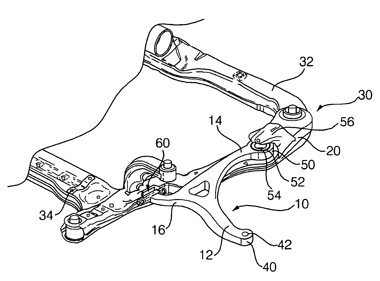
[0024]The lower arm, which is designated by reference numeral 10 in FIG. 1, includes a first rod 12 which is connected to a wheel of a vehicle, a second rod 14 which extends from the first rod 12 in one direction, and is connected to a front portion of a sub frame side member 20, and a third rod 16 which extends from the first rod 12 in a direction opposite to the second rod 14, and is connected to a rear portion of the sub frame side member 20.

[0025]The sub frame 30 includes a front member 32 which extends in a lateral direction of a vehicle body at a front side of the vehicle body. The side member 20 is also included in the sub frame 30. Although not shown, the sub frame 30 includes another side frame 20. The two side members 20 extend in a longitudinal direction of the vehicle body, and are connected to opposite ends of the front member 32, respectively. Th...


PUM


Abstract

A lower arm mounting structure of a vehicle suspension includes a first mount mounted to a wheel of a vehicle, a second mount mounted to a sub frame side member at one side of the sub frame side member, and a third mount mounted to the sub frame side member at the other side of the sub frame side member. The third mount is fastened to the sub frame side member at two points spaced apart from each other in a longitudinal direction of the sub frame side member by bolts. The lower arm mounting structure prevents the mounts from being displaced during the cornering of the vehicle. Accordingly, it is possible to reduce or eliminate the phenomenon that the front part of the vehicle is inclined, and to achieve an enhancement in vehicle handling performance.

Description

CROSS-REFERENCE TO RELATED APPLICATION[0001]This application claims priority to and the benefit of Korean Patent Application No. 10-2005-0103871 filed in the Korean Intellectual Property Office on Nov. 1, 2005, the entire contents of which are incorporated herein by reference.BACKGROUND OF THE INVENTION[0002]1. Field of the Invention[0003]The present invention relates to a lower arm mounting structure of a vehicle suspension, and, more particularly, to a lower arm mounting structure which provides two-point support for a lower arm of the vehicle suspension mounted to a sub frame side member.[0004]2. Description of the Related Art[0005]In a conventional lower arm mounting structure, a lower arm of a suspension may include a first rod which is connected to a wheel of a vehicle, a second rod which extends from the first rod in one direction, and is connected to one side of a sub frame side member, and a third rod 108 which extends from the first rod in a direction opposite to the secon...

Claims


Application Information

Patent Timeline
Patent Type & Authority Patents(United States)
IPC IPC(8): B60G3/04
CPCB60G7/02B60G2204/14B60G2204/1431B60G7/00B62D21/00
Inventor KIM, KI CHANG
Owner HYUNDAI MOTOR CO LTD
Why Eureka
Try Eureka