
Injection molding drop tip

a drop tip and injection molding technology, applied in the field of injection molding, can solve problems such as scrapping parts, and achieve the effect of reducing or eliminating color mixing, minimizing or eliminating scrapping

Inactive Publication Date: 2008-12-02
PLASTIC ENG & TECHN SERVICES
View PDF35 Cites 1 Cited by
  • Summary
  • Abstract
  • Description
  • Claims
  • Application Information

AI Technical Summary

Benefits of technology

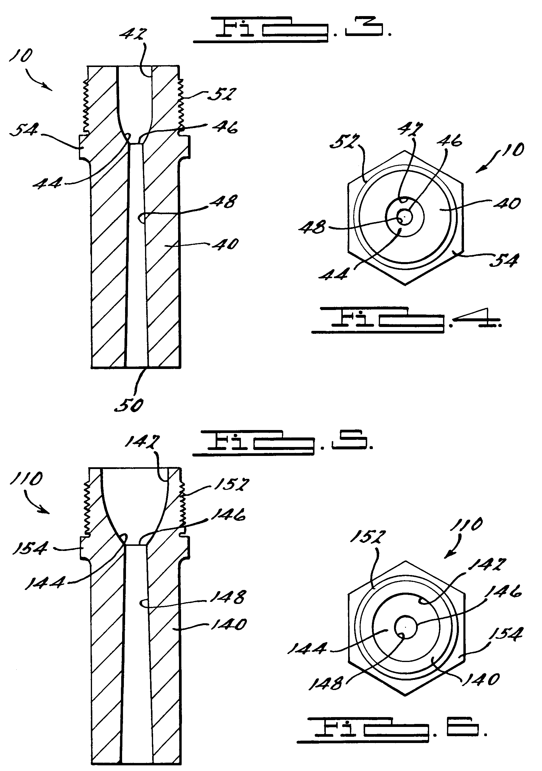
"The present invention is a drop tip for conveying injection molding material from a molding material supply into a mold. The drop tip has a new internal bore for molding of multiple colored parts, which eliminates retention of plastic material in the internal bore and reduces or eliminates mixing of colors for multiple color injection molding of parts. The drop tip also minimizes or eliminates scrap due to a change of colors as a result of the molding process."

Problems solved by technology

During the injection molding process, the first few parts molded will have a mix of the first color and the second color, resulting in scrap parts.

Method used


Image

  • Injection molding drop tip
  • Injection molding drop tip
  • Injection molding drop tip

Examples


Embodiment Construction

)

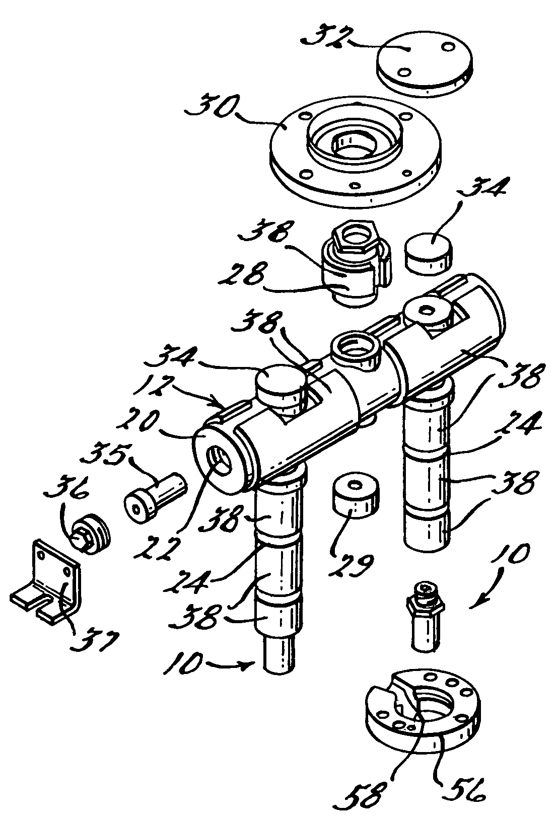
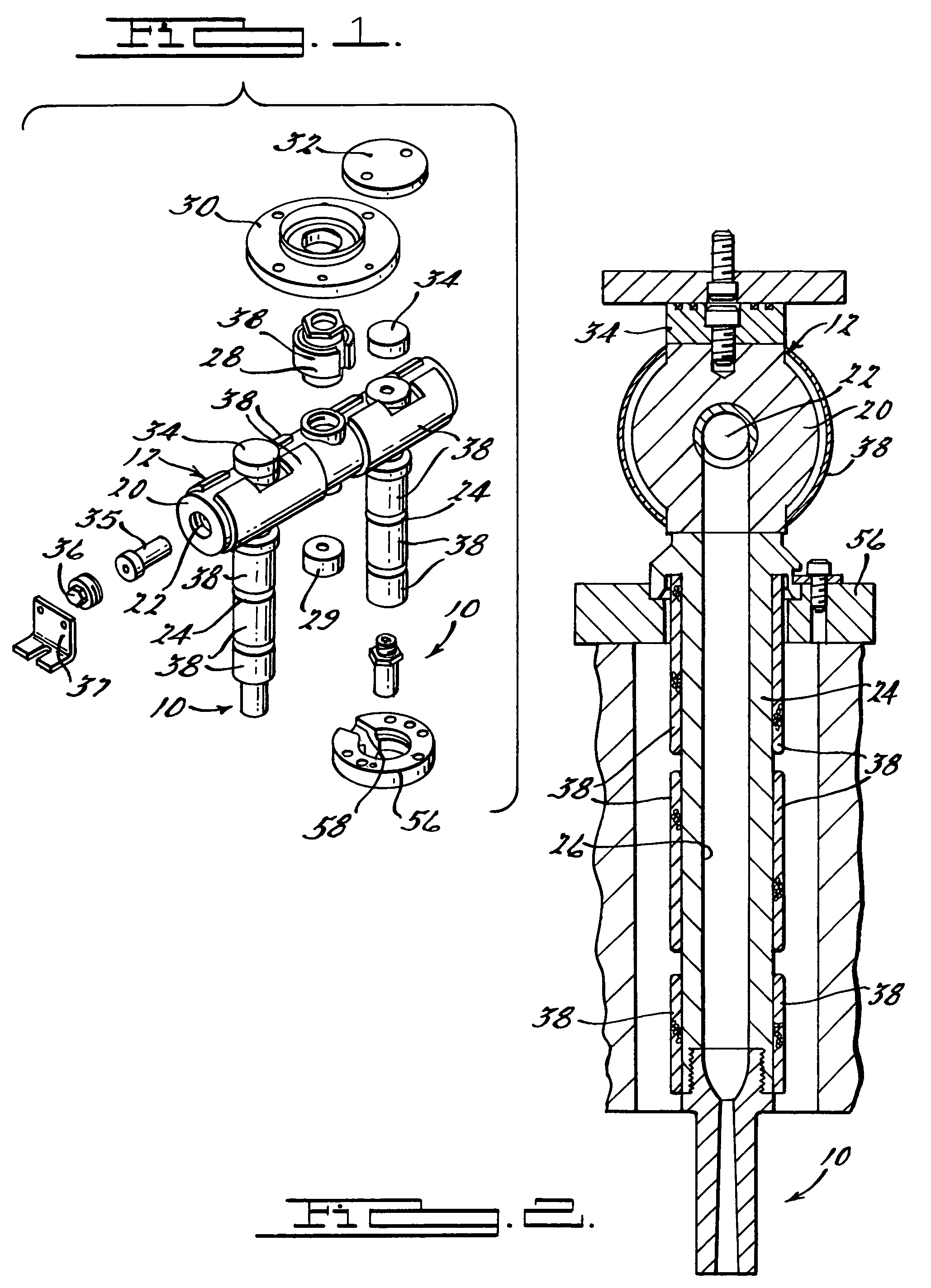
[0017]Referring to the drawings, and in particular FIGS. 1 and 2, one embodiment of a drop tip 10, according to the present invention, is shown for a manifold assembly, generally indicated at 12. The manifold assembly 12 is used for conveying an injection molding material from a molding material supply such as an injection molding machine (not shown) through the drop tip 10 and into a mold (not shown) for molding a part. The mold has a cavity (not shown) therein. It should be appreciated that a molten material (not shown) is introduced into the cavity via the drop tip 10.

[0018]The manifold assembly 12 includes a manifold 20 having a manifold flow passage 22. The manifold assembly 12 also includes as least one, preferably a plurality of drops or nozzles 24 extending downwardly from the manifold 20 and having a nozzle flow passage 26 fluidly communicating with the manifold flow passage 22. The flow passages 22 and 26 can be of any appropriate shape. The nozzle flow passage 26 narrows...


PUM

PropertyMeasurementUnit
diameteraaaaaaaaaa
diameteraaaaaaaaaa
diameteraaaaaaaaaa

Abstract

A drop tip is provided for conveying injection molding material from a molding material supply into a mold. The drop tip has a body including an internal bore and a drop passage extending from the internal bore. The internal bore has an arcuate lower end terminating in a gate to prevent retention of molten material therein.

Description

BACKGROUND OF THE INVENTION[0001]1. Field of the Invention[0002]The present invention relates generally to injection molding and, more particularly, to a drop tip for injection molding.[0003]2. Description of the Related Art[0004]Injection molding is a widely known manufacturing process used to produce a variety of parts. Injection molding involves introducing a molten material, for example a molten plastic or resin, into a cavity within a mold until the cavity is filled. The molten material hardens in the mold in the shape of inner surfaces of the cavity. After the molten material hardens or cures, the hardened or cured material is removed from the cavity.[0005]For injection molding, a manifold assembly is typically used for conveying molten material from a central injection portion or sprue to a number of cavities or to multiple points within one large cavity of the mold. An example of such a manifold assembly is disclosed in U.S. Pat. No. 4,964,795 to Tooman. In that patent, a ma...

Claims


Application Information

Patent Timeline
Patent Type & Authority Patents(United States)
IPC IPC(8): B29C45/20B29C45/27
CPCB29C45/278B29C45/20B29C45/22
Inventor TOOMAN, PATRICK A.
Owner PLASTIC ENG & TECHN SERVICES
Learn More