Method for manufacturing metallic reflector for LED package

a manufacturing method and technology for led packages, applied in semiconductor devices, light sources, light-emitting devices, etc., can solve the problems of difficult to realize desirable light efficiency, deterioration of reflector performance, and deterioration of reflector reflection performance, so as to prevent plating lifting, maintain reflector reflection performance, and improve manufacturing process

Active Publication Date: 2018-07-03
FIRSTENG CO LTD
View PDF5 Cites 3 Cited by
  • Summary
  • Abstract
  • Description
  • Claims
  • Application Information

AI Technical Summary

Benefits of technology

[0039]The present invention has been made in an effort to provide a metallic reflector manufacturing method for an LED package having advantages of simplifying the manufacturing process and reducing the manufacturing cost.
[0040]For achieving the above objects, a metallic reflector manufacturing method for an LED package of the present invention that a reflection surface is formed to surround an LED chip that is disposed on a substrate at a predetermined height and has a predetermined slant angle to reflect the light of the LED chip to the outside may include (a) preparing a metal plate, (b) processing a stamping reflector that includes a lower body and an upper body that is extended from an upper side of the lower body and is integrally formed with the lower body, a reflection surface that is slanted by a predetermined angle is formed at a central portion of the upper body and the lower body to reflect the light of the LED chip to the outside, and is processed by a stamping process such that a fixation portion is formed to fix the lower body on a substrate that the LED chip is mounted on, (c) sequentially plating Ni and Ag on the reflection surface or the stamping reflector surface, wherein the stamping processing of the step (b), may include (b-1) a piercing step that pierces a base hole for each stage of the stamping process at an upper and lower edge of the metal plate in a length direction of the metal plate, (b-2) a drawing step that forming the reflection surface on the metal plate between the base holes, (b-3) a first noting step that eliminates a scrap from the metal plate, (b-4) a half etching step that forms the fixation portion, and (b-5) a second notching step that forms the opening. In accordance with an exemplary embodiment of the present invention, a fixation portion that can fix the metallic reflector is disposed on the reflector such that the performance and the durability of the LED package can be improved.
[0041]And, multi-layered plating is formed on the metallic reflector surface such that the lifting of the plating can be prevented and the reflection performance of the reflector can be maintained.

Problems solved by technology

However, because the inner wall 111 of the opening 15 includes a synthetic resin such as PPA, the color thereof is changed by the light and the heat that are emitted from the LED chip 14, the reflection rate is deteriorated, and therefore it is hard to realize desirable light efficiency.
However, when the reflection layer 282 of the metallic reflector 28 is formed by aluminization, the aluminization is direct performed on the metallic surface, and therefore the reflection layer 282 is lifted such that the reflection performance is deteriorated and the product quality is ruined.
And, when the reflector 28 is combined by a screw, because the reflector 28 size is small, there is a problem that a screw cutting for the reflector 28 and the substrate is not easy.
However, because the reflector 40 is sealed by the housing 10 and the encapsulant 30, it is yet hard to radiate heat to the outside such that the performance, the durability, and the reliability of the LED package 1 are deteriorated.
However, the die casting forming needs an expensive facility due to metallic melted material, and also there is a problem that the die casting mold price is expensive.
And, because specific metal material that the melding point is low such as Mg, Zn, or Al can be applied to the die casting forming, a kind of metal is limited in manufacturing the metallic reflector.
Also, overall manufacturing process such as metal melting, and trimming process is difficult due to the die casting forming, and barrel polishing and chemical polishing have to be performed after the die casting forming.
And, because the conventional reflector is manufactured by the die casting forming, nonferrous metals such as Zn that the melting point is low has to be used, and therefore raw material cost is high, the process has to be mass production product, and there is a problem that the post processing is not easy.
Also, because the product that is manufactured by the die casting forming, the inside constitution of the metal is weak and there is a problem that the product is weak from the high temperature or an impact.

Method used


Image

  • Method for manufacturing metallic reflector for LED package
  • Method for manufacturing metallic reflector for LED package
  • Method for manufacturing metallic reflector for LED package

Examples


Embodiment Construction

[0061]Hereinafter, referring to the drawings, a desirable exemplary embodiment will be described according to the present invention.

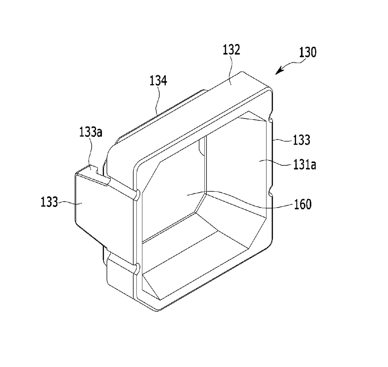
[0062]FIG. 5 is a front perspective view showing an exemplary embodiment of a metallic reflector that a metallic reflector manufacturing method for an LED package is applied thereto according to the present invention, and FIG. 6 is a front view of FIG. 5, and FIG. 7 is a rear perspective view of FIG. 5.

[0063]Also, a cross-sectional view showing an LED package that a metallic reflector of FIG. 5 is applied thereto is shown in FIG. 8.

[0064]Referring to FIG. 5 and FIG. 8, a metallic reflector 130 that a metallic reflector manufacturing method for an LED package is applied thereto according to the present invention includes a reflection surface that has a predetermined height to surround an LED chip 120 that is mounted on a substrate 110 and has a reflection surface that is slanted by a predetermined angle to reflect the light of the LED chip 120 to the out...


PUM

PropertyMeasurementUnit
heightaaaaaaaaaa
lengthaaaaaaaaaa
voltageaaaaaaaaaa

Abstract

A metallic reflector manufacturing method for an LED package. The method includes preparing a metal plate, and processing a stamping reflector that includes a lower body and an upper body that is extended from an upper side of the lower body and is integrally formed with the lower body. A reflection surface that is slanted by a predetermined angle is formed at a central portion of the upper body and the lower body to reflect the light of the LED chip to the outside. A fixation portion is formed to fix the lower body on a substrate that the LED chip is mounted on. The method further includes sequentially plating Ni and Ag on the reflection surface or the stamping reflector surface. The stamping processing includes a piercing step, a drawing step, a first noting step, a half etching step that forms the fixation portion, and a second notching step.

Description

CROSS-REFERENCE TO RELATED APPLICATION[0001]This application claims priority to and the benefit of Korean Patent Application No. 10-2014-0061902 filed in the Korean Intellectual Property Office on May 22, 2014, the entire contents of which are incorporated herein by reference.BACKGROUND OF THE INVENTION[0002](a) Field of the Invention[0003]The present invention is related to a metallic reflector manufacturing method for an LED package. More particularly, the present invention relates to a metallic reflector manufacturing method for an LED package that the manufacturing process is very simple and the cost is cheap.[0004](b) Description of the Related Art[0005]Generally, an LED (Light Emitting Diode) is an element that an electron meets hole to emit light in a P-N semiconductor junction, and the LED uses low voltage and current to enable continuous light emitting and has many merits such as low power consumption compared to other light source.[0006]The LED is manufactured to have a ge...

Claims


Application Information

Patent Timeline
Patent Type & Authority Patents(United States)
IPC IPC(8): H01L33/00B21D35/00H01L33/60F21K9/90F21K9/68B21D28/02B21D28/32
CPCH01L33/005H01L33/60Y10T29/49988B21D28/02B21D28/32B21D35/001F21K9/68F21K9/90H01L2224/48091H01L2224/48247H01L2933/0025H01L2933/0033H01L2933/0058H01L2924/00014
Inventor KIM, YUNG CHEONNAM, DEOK HEEPARK, MIN CHULPARK, HAE CHULKANG, BAEK WON
Owner FIRSTENG CO LTD
Why Eureka
Try Eureka