Portable kiln

a kiln and portable technology, applied in the field of kilns, can solve the problems of difficult movement, heavy kiln, and inability to use outside temperatures, and it may not be desirable to leave the kiln in a useable position,

Active Publication Date: 2008-12-02
HOHENSHELT
View PDF27 Cites 29 Cited by
  • Summary
  • Abstract
  • Description
  • Claims
  • Application Information

AI Technical Summary

Benefits of technology

[0014]The platform base is attached to the outer shell below the oven portion. The lid is adapted to at least partially cover the oven space. The hinge assembly has a first portion and a second portion. The first hinge portion is attached to the outer shell. The second hinge portion is attached to the lid. The lid is pivotably coupled to the outer shell by the hinge assembly. When the lid is in a fully open position, the second hinge portion presses against the first hinge portion to limit a pivotal movement range of the lid so that the lid can rest in the fully open position with the lid extending upwards and tilted away from the kiln.

Problems solved by technology

However, the use of such blocks typically causes the kiln to be very heavy and difficult to move.
With the use of conventional insulation (ceramic blocks), the outside surface of a conventional kiln may experience temperatures as hot as 400° F. However, such outside temperatures may not be safe for use within a home by hobbyists due to risks of fire or risks of human contact with the outer surface of the kiln.
Also, many home hobbyists or small laboratories that only occasionally use a kiln may not have a suitable work space or it may not be desirable to leave a kiln in a useable position (i.e., away from the wall and away from other objects that may catch fire or melt if too close to an operating kiln) when it is not in use.
For example, a hobbyist may desire to store the kiln in a closet or move the kiln through a doorway to another room for storage, but conventional kilns are not designed for such movement on a regular basis.

Method used


Image

  • Portable kiln
  • Portable kiln
  • Portable kiln

Examples


Embodiment Construction

[0024]Referring now to the drawings, wherein like reference numbers are used herein to designate like elements throughout the various views, a preferred embodiment of the present invention is illustrated and described. As will be understood by one of ordinary skill in the art, the figures are not necessarily drawn to scale, and in some instances the drawings have been exaggerated and / or simplified in places for illustrative purposes only. One of ordinary skill in the art will appreciate the many applications and variations of the present invention in light of the following description of a preferred embodiment of the present invention. The preferred embodiment discussed herein is an illustrative example of the present invention and does not limit the scope of the invention to the preferred embodiment shown.

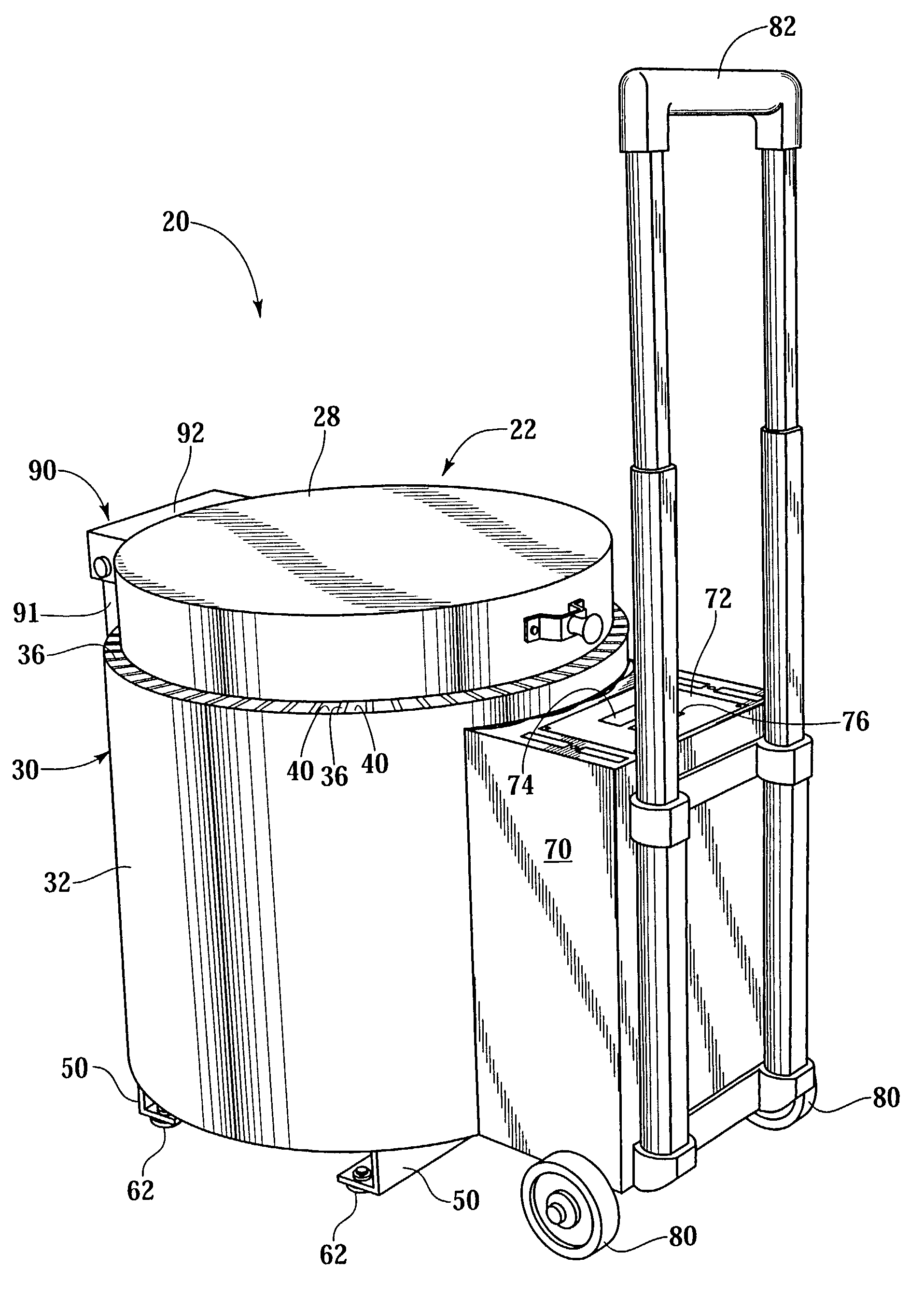
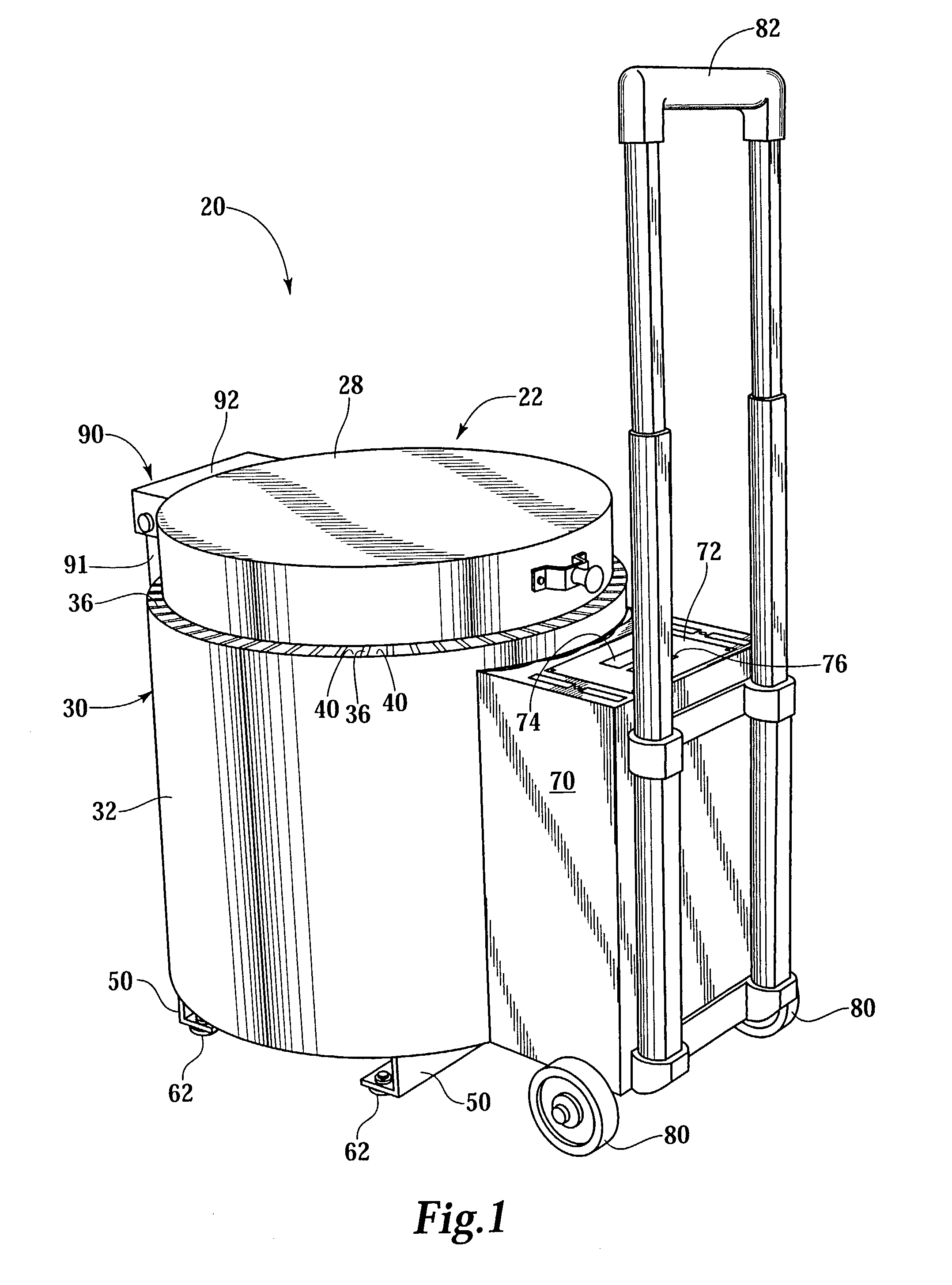
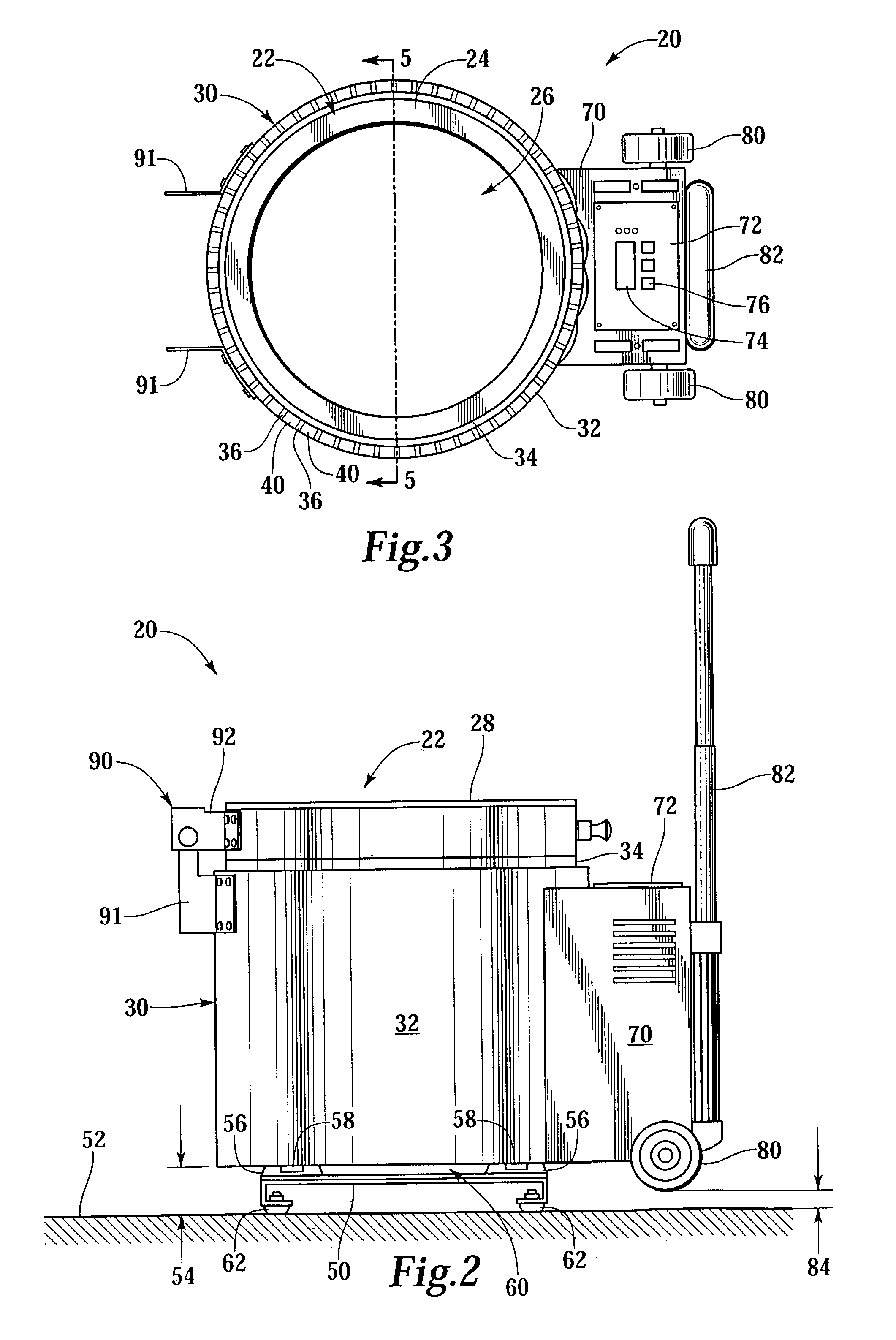
[0025]FIG. 1 is a front perspective view of the portable kiln 20, and FIG. 2 is a side view of the portable kiln 20. The kiln 20 has an oven portion 22 having an insulating sidewa...


PUM


Abstract

A portable kiln has a set of wheels, a handle and a platform base. The wheels and the handle are attached on a first side of the kiln so that the kiln can be tilted and rolled on the wheels using the handle. The platform base provides a spaced distance between the wheels and the floor when the kiln is sitting upright in an operational position. The kiln may also include a metal outer shell wrapped about an oven portion. The outer shell has a shell sidewall radially spaced from the oven portion sidewall, which forms an annular air channel between the outer shell sidewall and the oven portion. The outer shell has a C-shaped cross-section and it has upper and lower vent openings for the air channel. A hinge assembly allows a lid of the kiln to rest in an open position.

Description

BACKGROUND OF THE INVENTION[0001]The present invention relates to kilns. In one aspect, it relates to a small, lightweight and portable kiln that may be used by home artists and hobbyists.[0002]Kilns are often used for firing pottery or ceramics, both commercially and by hobbyists. Kilns are also used in laboratories to provide specific heat cycles for forming materials and / or testing already-formed materials. Kilns are used by custom knife artisans for creating and / or heat treating knife blades. There are many other possible uses for kilns, including but not limited to: annealing, china painting, enameling, glass fusing, glass sagging, glass shaping, heat treating, jewelry fabrication, porcelain, silver clay, and stoneware, for example. The sizes and shapes of currently available kilns vary widely. Usually the sizes and shapes of kilns correspond to the intended use of the kiln.[0003]Internal temperatures within a kiln may be as hot as 2300° F. during operation of the kiln. Usually...

Claims


Application Information

Patent Timeline
Patent Type & Authority Patents(United States)
IPC IPC(8): F27B9/00F27B17/00F27B17/02F27D1/00
CPCF27B17/005F27B17/02
Inventor HOHENSHELT, JOHN S.GIESELMAN, ROBERT L.BEAUMONT, DAVID T.
Owner HOHENSHELT
Why Eureka
Try Eureka