Filter device

a filter device and filter technology, applied in the direction of filtration separation, moving filter element filter, separation process, etc., can solve the problems of affecting the performance of the filter device, the difficulty of cleaning the filter device, so as to achieve the effect of being particularly easy to perform and sa

Active Publication Date: 2008-12-02
HYDAC FILTERTECHNIK GMBH
View PDF12 Cites 60 Cited by
  • Summary
  • Abstract
  • Description
  • Claims
  • Application Information

AI Technical Summary

Benefits of technology

[0005]An object of the present invention is to provide a filter device in which the measures to be carried out to change the filter element can be performed especially easily and safely, so that trouble-free operation of the fluid means is ensured.
[0006]According to the present invention, this object is basically achieved by a filter device where a bayonet catch is provided as the fastening means, by which the filter housing can be detachably fastened to the fluid means. By rotary motion of the filter housing when the bayonet catch is being locked and released, a blocking element can be controlled which blocks and clears the pertinent fluid connection. The filter can then be changed with a maximum of safety and especially simply and easily. This easy changing is achieved in that blocking and clearing of the fluid connection take place automatically when the filter housing is being mounted and dismounted. This operation in turn takes place in an especially simple and easy manner by releasing and locking the bayonet catch.
[0007]Based on use of a bayonet catch as the fastening means and of the automatic blocking of the fluid connections when the bayonet catch is released, all the actuation processes in conjunction with replacing a used filter element can be carried out in a few seconds. The filter housing containing the used filter element can be removed as a whole from the fluid means by releasing the bayonet catch without separate measures being necessary at the fluid connections of the fluid means. Likewise, the attachment of a filter housing containing an unused filter element is effected in a correspondingly short period of time by locking the bayonet catch, because the fluid connections are automatically cleared by the locking process.
[0008]In embodiments characterized by an especially simple and compact design, the blocking element is a rotary disk valve which is pivoted on the fluid means. In this configuration, the rotary motions which take place when the bayonet catch is actuated can be converted especially easily into the corresponding rotational-control motions of the rotary disk valve.

Problems solved by technology

Hydraulic oil is fouled during installation and when the respective hydraulic system is started up.
In addition to this initial fouling, fouling during operation can occur, for example, by penetration of dirt at the hydraulic tank due to inadequate tank ventilation, pipe penetrations, piston rod seals, and the like.
In the known solutions, tedious and time-consuming measures must be carried out in conjunction with changing the filter housing.
Thus, the pipes which belong to the connection system must be separated from one another and sealed tight in a complicated process.
There is also the danger that larger amounts of fluid will escape from the filter housing and / or fluid means as a type of leaking oil flow when the filter housing is being dismounted.
This leaking leads to environmental pollution problems.

Method used


Image

  • Filter device
  • Filter device
  • Filter device

Examples


Embodiment Construction

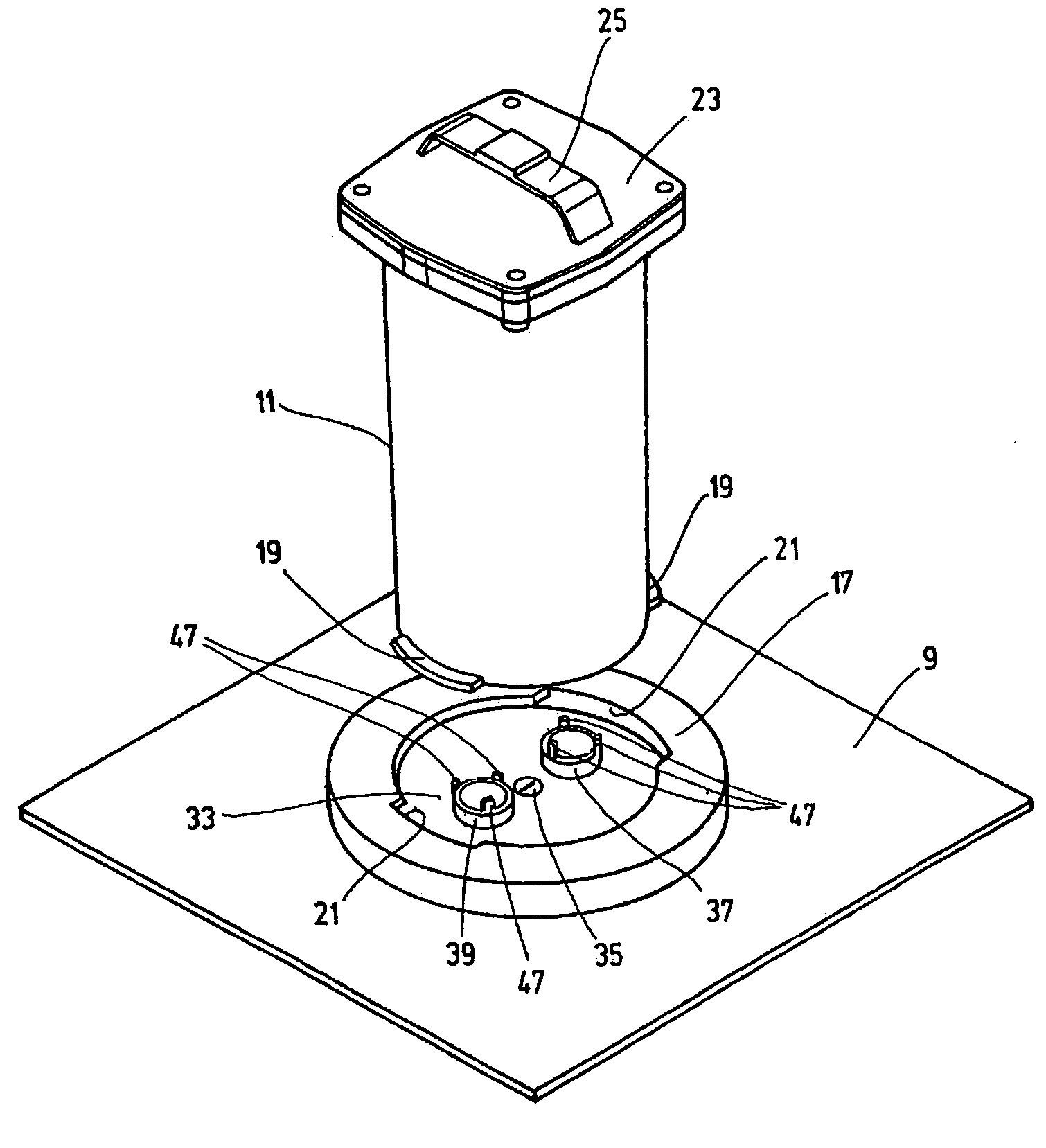
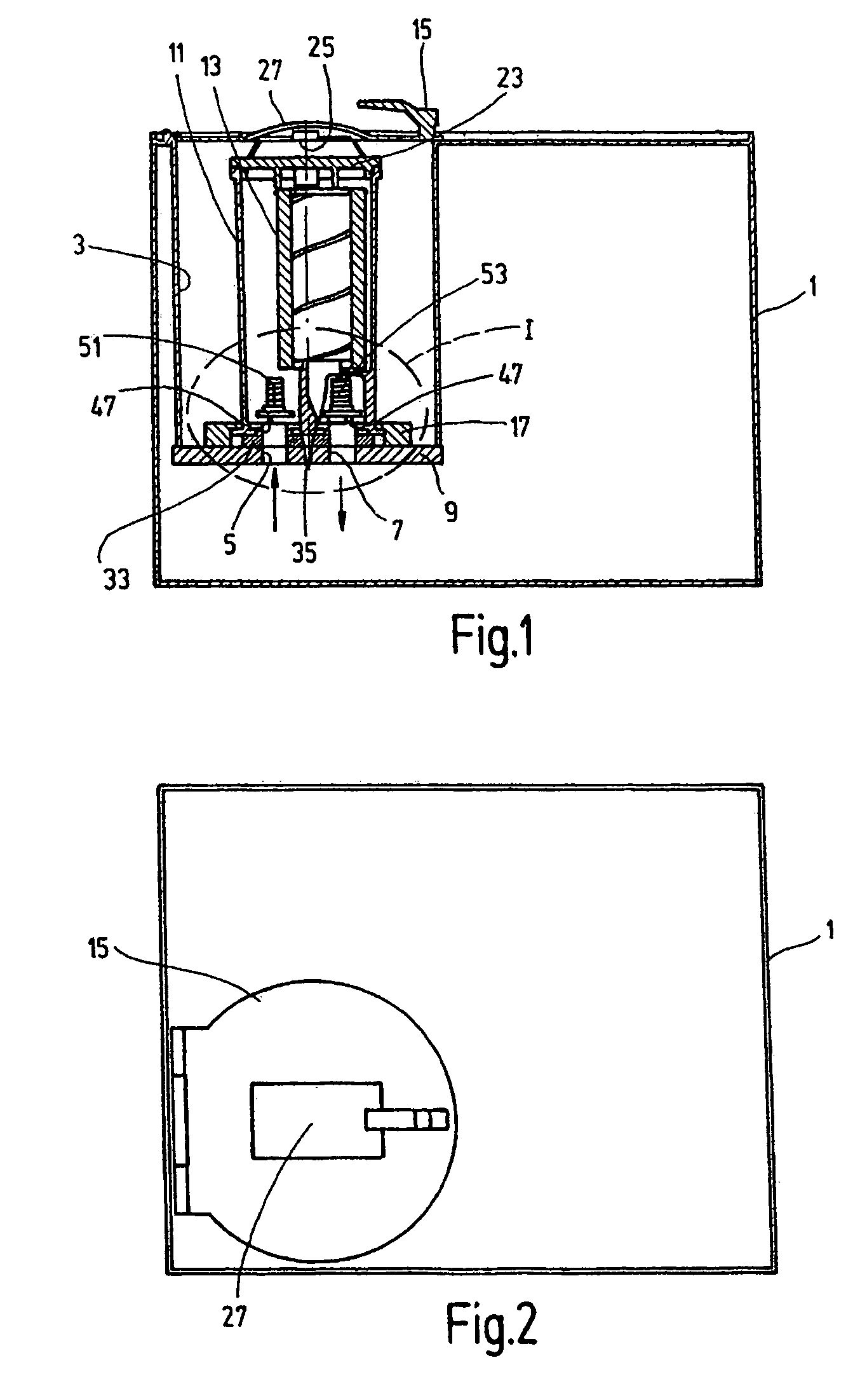
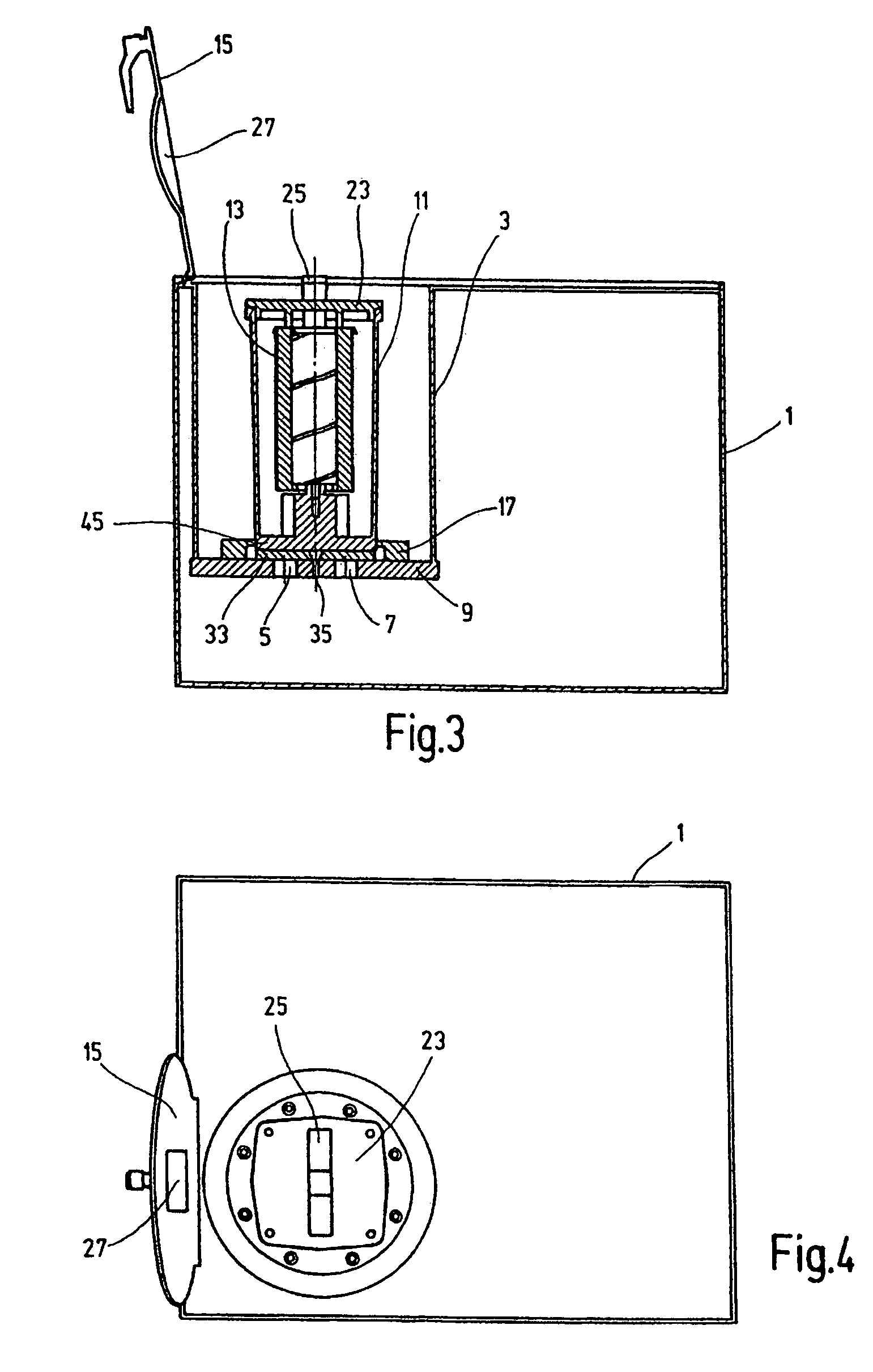
[0018]FIGS. 1 to 4 show a fluid means in the form of a hydraulic tank 1 with a separate tank compartment 3 built into it and connected to the remaining tank contents simply by the fluid connections 5 and 7. Otherwise, tank compartment 3 is sealed relative to the remaining tank contents. The fluid connections 5 and 7 are located on the bottom-side end of the tank compartment 3, which end is formed by a flat connecting plate 9. The connecting plate 9 forms the carrier for the filter housing 11 of the filter device of the present invention, which filter housing can be attached to the plate by a detachable fastening device. For the filter housing 11 which is in the operating position and which is attached to the connecting plate 9, the fluid connection 5 forms the inlet for supply of the fluid to be cleaned to the dirty side in the interior of the filter housing 11. The outflow of cleaned fluid after it has passed through the filter element 13 in the filter housing takes place through t...


PUM

PropertyMeasurementUnit
rotationaaaaaaaaaa
timeaaaaaaaaaa
period of timeaaaaaaaaaa

Abstract

A filter device includes at least one filtering element arrangeable in a filter housing (11) connectable to a hydraulic device (9), in particular a hydraulic tank. The tank is connectable to the filter housing through hydraulic connections (37, 39) by a connection system in such a way that a fluid is enabled to circulate. The filter housing is removably mounted on the hydraulic device (9) by a fixing unit. The fixing unit is embodied in the form of a bayonet fitting (17, 19) which is lockable and detachable by the filter housing (11) rotation. The connection system has at least one movable locking element which locks in the locking position the hydraulic connection (37, 39) associated with it, and releases the connection after displacement in the open position. The locking element is displaceable in a sealing or opening position by rotational motions of the housing (11) for detaching and locking the bayonet fitting (17, 19).

Description

FIELD OF THE INVENTION[0001]The present invention relates to a filter device comprising at least one filter element which can be held in a filter housing connected to carry fluid by fluid connections to a fluid means, especially in the form of a hydraulic tank, via a connection system. The filter housing can be detachably fastened to the fluid means by a fastening means.BACKGROUND OF THE INVENTION[0002]Filter devices of this type are readily available on the market in a plurality of designs and versions. They are used, among other purposes, to filter dirt in fluids, such as hydraulic oil, out of these fluids. Hydraulic oil is fouled during installation and when the respective hydraulic system is started up. In addition to this initial fouling, fouling during operation can occur, for example, by penetration of dirt at the hydraulic tank due to inadequate tank ventilation, pipe penetrations, piston rod seals, and the like. To the extent fouling within the fluid stored in the hydraulic...

Claims


Application Information

Patent Timeline
Patent Type & Authority Patents(United States)
IPC IPC(8): B01D27/08B01D35/153B01D35/157B01D35/30B01D29/96B01D35/027
CPCB01D29/96B01D35/0276B01D35/153B01D2201/4015
Inventor KLEIN, VOLKMARDAUB, JOEL
Owner HYDAC FILTERTECHNIK GMBH
Why Eureka
Try Eureka