Planing boat and method for manufacturing the same

a technology for boating and boating, applied in the field of boating, can solve problems such as and achieve the effect of preventing the boat from rocking

Inactive Publication Date: 2017-11-16
IZUME MASAYUKI
View PDF2 Cites 2 Cited by
  • Summary
  • Abstract
  • Description
  • Claims
  • Application Information

AI Technical Summary

Benefits of technology

[0023]With the planing boat in accordance with the present invention, the introduction of the water from outside of the hull into the tank when the boat is moored, and the discharge of the water from inside of the tank to the outside of the hull at the sailing are performed associated with the stoppage and the sailing of the boat, respectively, whereby the boat is prevented from rocking when moored, and an operation to prevent the boat from acting as an impediment to the sailing is trouble-free.

Problems solved by technology

Under the circumstances, preventing the boat from rocking when moored has been an issue to address.

Method used


Image

  • Planing boat and method for manufacturing the same
  • Planing boat and method for manufacturing the same
  • Planing boat and method for manufacturing the same

Examples


first embodiment

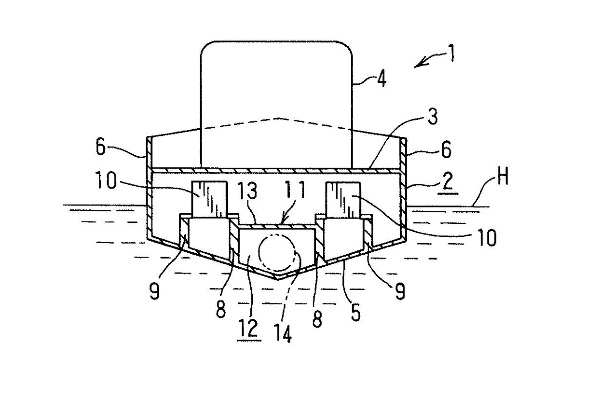
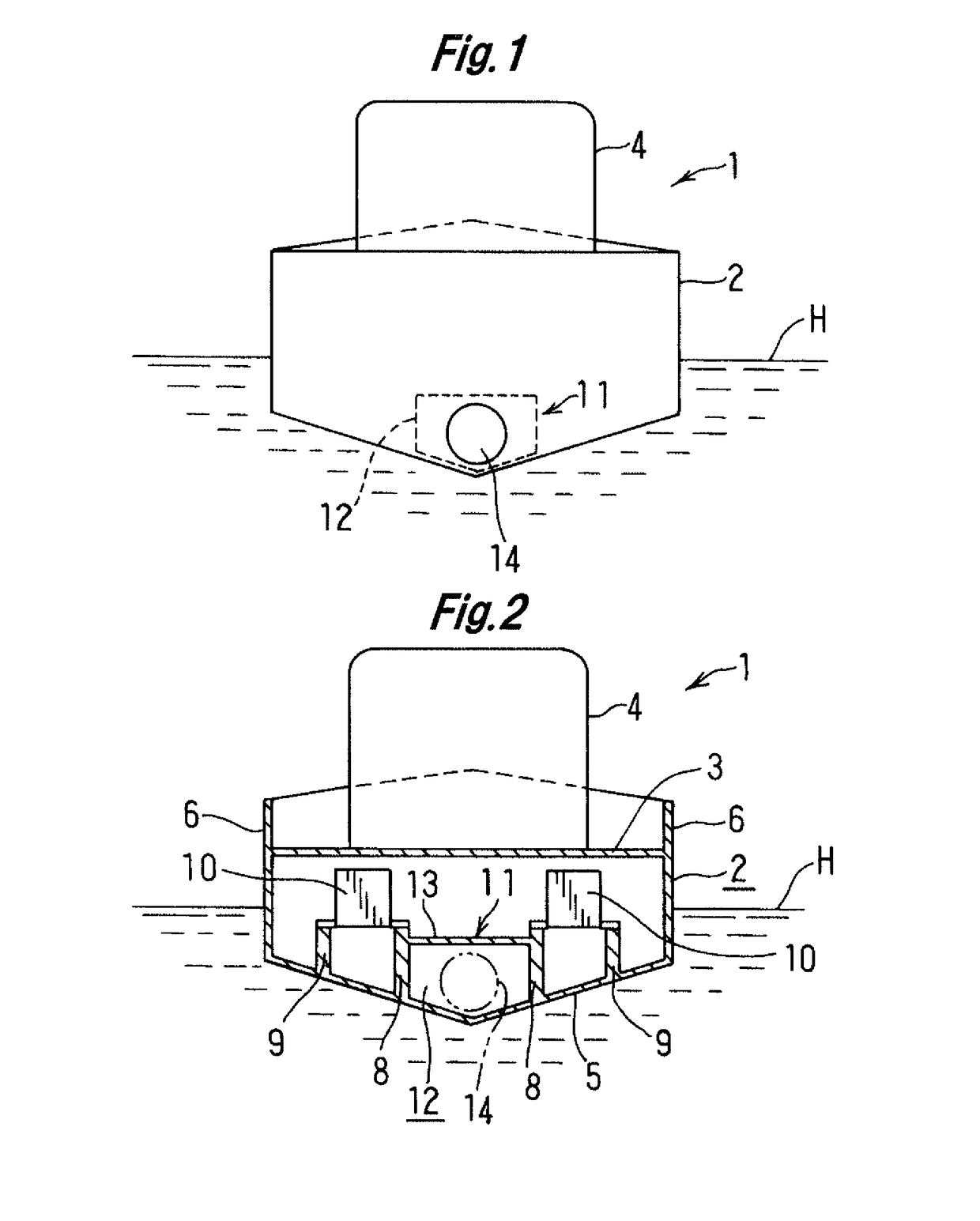
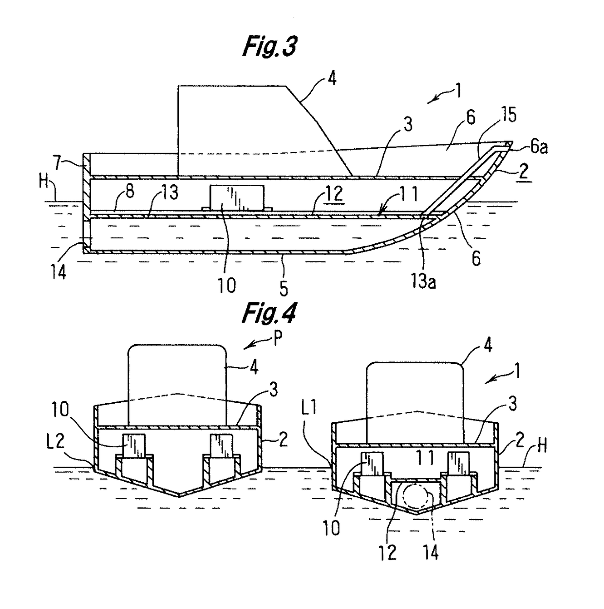
[0035]FIG. 1 to FIG. 3 show a planing boat, when moored, according to the present invention. A boat (1) includes: a hull (2) made of fiberglass reinforced plastic (FRP); a deck (3) made of FRP and joined to an outer edge of an upper portion of the hull (2); and a cabin (4) provided to project from the deck (3).

[0036]The hull (2) includes: a bottom plate (5) that forms the bottom of the boat; right and left side plates (6) that form the sides of the boat and a bow; a transom plate (7) that forms a stern; and four longitudinal vertical plates (8) and (9) each extending between the transom plate (7) and forward portions of the right and left side plates (6) along a sailing direction and each having a lower surface that is fixed to an upper surface of the bottom plate (5).

[0037]The four longitudinal vertical plates (8) and (9) are arranged symmetrically in the right and left direction. Between each pair of the longitudinal vertical plates (8) and (9), an engine (10) supported by an engi...

second embodiment

[0046]FIG. 6 to FIG. 8 show a boat, when moored, according to the present invention.

[0047]A boat (20) according to the second embodiment differs from the boat (1) according to the first embodiment in that an engine (26) is provided at the center in the right and left direction. The shape of the hull (2), including the longitudinal vertical plates (8) and (9), is the same as that of the first embodiment.

[0048]The boat (20) as described above has the same structure of the conventional planing boat, but the planing boat (20) in accordance with the present invention further includes an anti-rocking device (21).

[0049]The anti-rocking device (21) has right and left tanks (22) for storing water. Between upper ends of each pair of the two longitudinal vertical plates (8) and (9), each pair being provided at the right or left part of the boat (20), a top plate (23) is laid. Each of the two right and left pairs of longitudinal vertical plates (8) and (9), the top plate (23), a part of the bot...

third embodiment

[0054]FIG. 10 shows the boat (during the sailing) according to the present invention. When the boat starts sailing and the sailing speed exceeds a certain value, the bow rises above the surface of the water and the boat starts pushing water away at an area behind the stern, as shown in FIG. 5. At this time, when the closed lid (26) is opened, the boat continues sailing with no water flowing through the through hole (14) into the tank (12).

[0055]In the above embodiments, the longitudinal vertical plates (8) and (9) are not limited to those shown in the drawings, and the tank may be provided by using existing longitudinal vertical plates as appropriate. In addition, when required, any longitudinal material as a separate component may be added for forming the tank.


PUM


Abstract

A planning boat includes at least one tank provided on a bottom of the boat. The tank has, at a stern side, a wall through which a through hole is provided below a waterline. A hull of the planning boat includes a bottom plate that forms the bottom of the boat, right and left side plates that form sides of the boat and a bow, a transom plate that forms a stern, and a plurality of longitudinal vertical plates. The plurality of longitudinal vertical plates each extend between the transom plate and forward portions of the side plates along a sailing direction and each have a lower surface that is fixed to an upper surface of the bottom plate. The tank is formed by using the pair of longitudinal vertical plates of the existing planning boat.

Description

TECHNICAL FIELD[0001]The present invention relates to a planing boat, and more particularly, to a planing boat that is prevented from rocking when moored.BACKGROUND ART[0002]Small-sized planing boats such as various types of fishing boats and pleasure boats are used for fishing, while they are moored on a water surface of the sea or lakes. Under the circumstances, preventing the boat from rocking when moored has been an issue to address. Patent Literature 1 discloses a hull stabilizing mechanism (anti-rocking device) including a rudder blade and a rudder blade moving mechanism, in which placing the rudder blade into water prevents the boat from rocking while removing the rudder blade from the water when sailing prevents the rudder blade from producing sailing resistance.CITATION LISTPatent Literature[0003]Patent Literature 1: Japanese Unexamined Patent Application Publication No. 2004-58772SUMMARY OF INVENTIONTechnical Problem[0004]To prevent the boat from rocking when moored, it is...

Claims


Application Information

Patent Timeline
Patent Type & Authority Applications(United States)
IPC IPC(8): B63B43/06B63B39/02B63B1/18B63B3/26B63B9/04B63B43/14B63B59/02
CPCB63B43/06B63B39/02B63B1/18B63B43/14B63B9/04B63B59/02B63B2003/265B63B83/40B63B19/00B63B39/03B63H21/24
Inventor IZUME, MASAYUKI
Owner IZUME MASAYUKI
Why Eureka
Try Eureka