Top pot assembly

a technology for top pots and assembly parts, applied in the direction of sealing/packing, earthwork drilling and mining, borehole/well accessories, etc., can solve the problems of increasing drilling operation expenses, reducing the operating time of drilling rigs, and increasing drilling downtime, so as to increase assembly efficiency, reduce the amount of down time, and increase the life of bearings, seals and other internal components.

Active Publication Date: 2019-08-27
PRUITT TOOL & SUPPLY
View PDF4 Cites 2 Cited by
  • Summary
  • Abstract
  • Description
  • Claims
  • Application Information

AI Technical Summary

Benefits of technology

[0032]Another object of the present invention is to increase efficiency of the assembly and disassembly of the rotating head assembly to decrease the amount of down time due to necessary repairs of the rotating head assembly.
[0033]Another object of the present invention is to increase the life of bearings, seals, and other internal components by preventing debris from entering the bearings, seals, and other internal components.
[0034]Another object of the present invention is to allow for the trouble free operation of the rotating head assembly for the rig personnel.
[0035]Another object of the present invention is to create a safer work environment for rig personnel.
[0036]Another object of the present invention is to simplify the method of assembly of the rotating head assembly.
[0037]Another object of the present invention is to allow a quick change system that will save valuable time on the rig, thus eliminating time in which the rig is inoperable to reduce nonproductive time.

Problems solved by technology

Thus, known rotating heads increased downtime of the drilling and reduced the operating time of the drilling rig to increase expenses of the drilling operation.

Method used


Image

  • Top pot assembly
  • Top pot assembly
  • Top pot assembly

Examples


Embodiment Construction

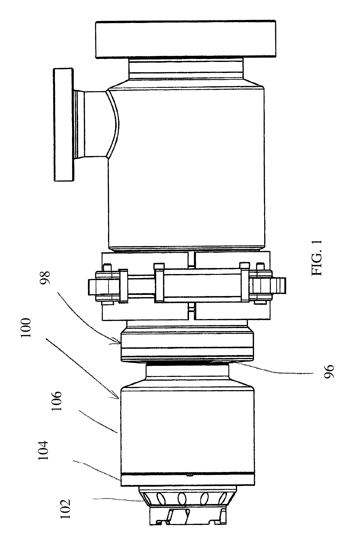
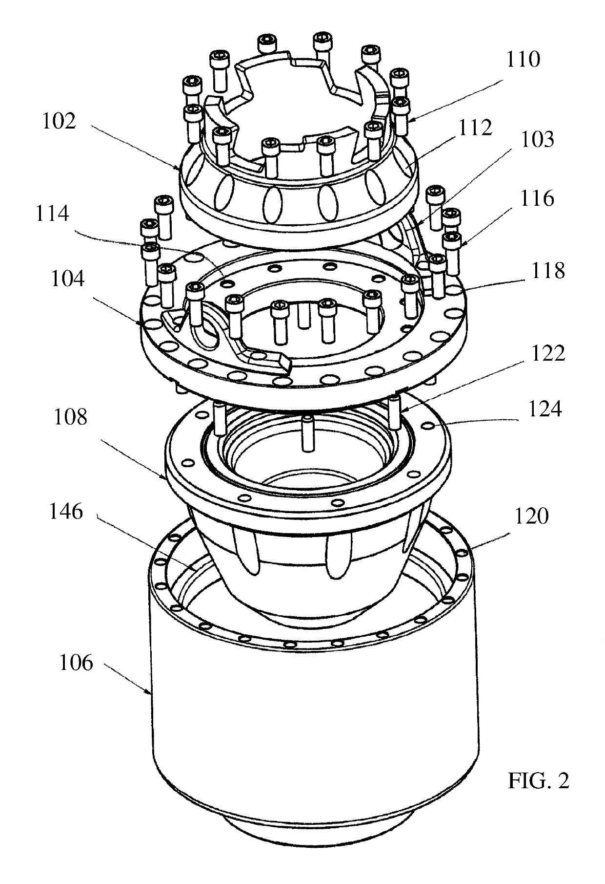
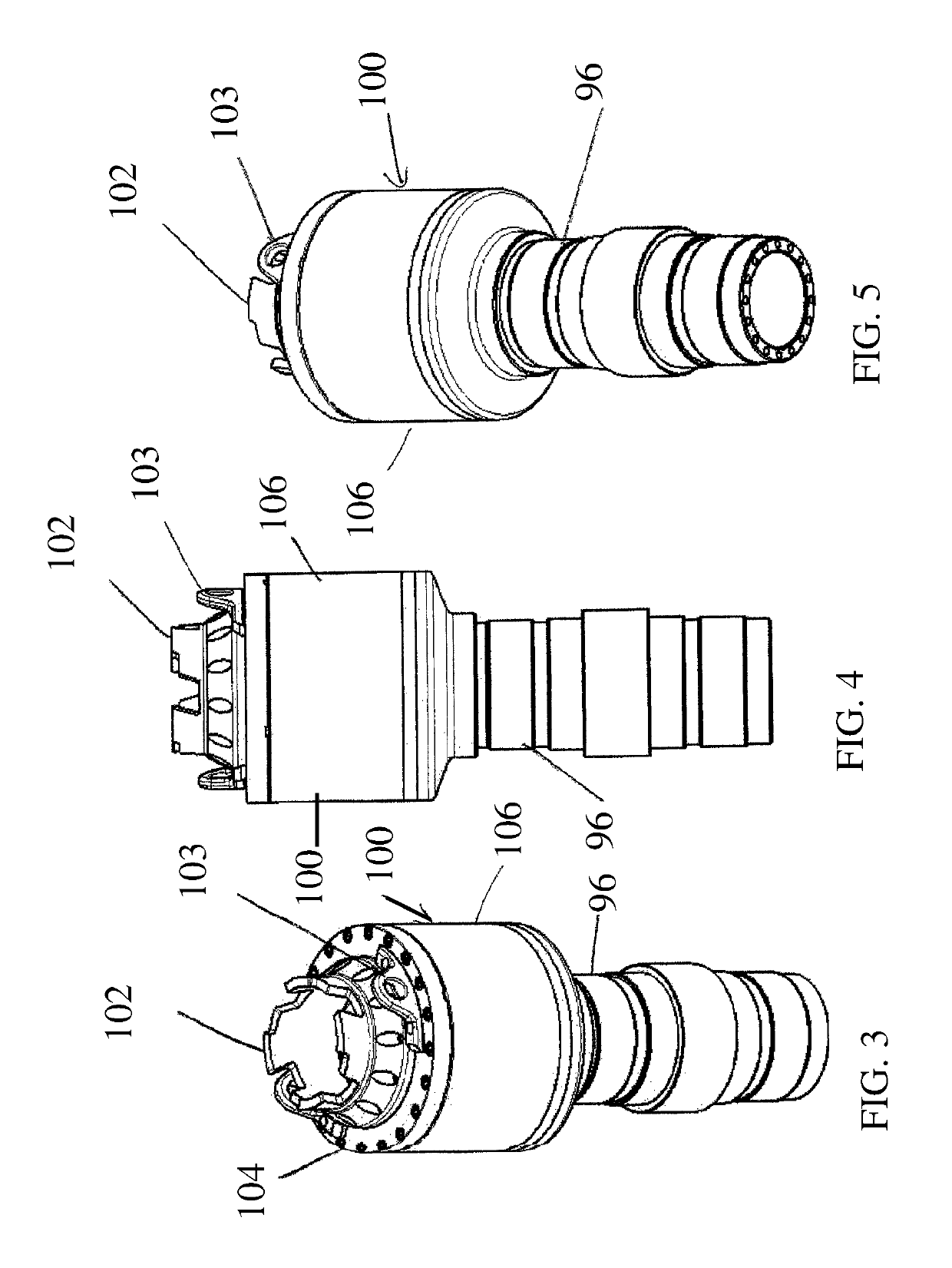
[0061]The present invention relates to rotating heads for oil and gas wells and more particularly, to an improved top pot assembly 100 that utilizes an attachment body 104 for attaching the rubber and the driving head to a bearing assembly for rotation with the inner barrel. Referring to FIG. 1, the top pot assembly of the present invention is generally illustrated by reference numeral 100. The top pot assembly 100 is characterized by a driving head 102, an attachment body 104, a rubber 108, and a housing 106. The housing 106 attaches to the inner barrel 96 of the bearing assembly 98. The attachment body 104 simplifies the replacement of the rubber 108 on the drilling assembly. The attachment body 104 provides a driving receiver for attachment of the driving head 102 to the attachment body 104. A stripper receiver of attachment body 104 secures the rubber 108 to the attachment body 104. The attachment body 104 secures to the housing 106. The housing 106 attaches to the inner barrel ...


PUM


Abstract

An improved top pot assembly utilizes an attachment body for attaching the rubber to a bearing assembly for rotation with the inner barrel. The attachment body simplifies the replacement of the rubber on the drilling assembly. The attachment body provides a guide that slopes downward into the central aperture and the bore to guide the mandrel and drilling string towards the bore. The attachment body also provides a stripper receiver for attachment of the rubber to the attachment body. The attachment body attaches to the housing which attaches to the bearing assembly for rotation of the rubber and the inner barrel.

Description

CROSS-REFERENCE TO RELATED APPLICATIONS[0001]This application is a continuation in part of U.S. patent application Ser. No. 14 / 076,096 filed on Nov. 8, 2013 entitled TOP POT ASSEMBLY which is a continuation of U.S. patent application Ser. No. 12 / 804,107 filed on Jul. 14, 2010 entitled TOP POT ASSEMBLY.[0002]This application is related to U.S. patent application Ser. No. 12 / 072,929 filed on Feb. 29, 2008 entitled DUAL RUBBER CARTRIDGE and U.S. patent application Ser. No. 12 / 074,151 filed on Feb. 29, 2008 entitled EXTENDED WEAR BALL LOCK FOR ROTATING HEAD.STATEMENT REGARDING FEDERALLY SPONSORED RESEARCH OR DEVELOPMENT[0003]Not Applicable.REFERENCE TO A MICROFICHE APPENDIX[0004]Not Applicable.RESERVATION OF RIGHTS[0005]A portion of the disclosure of this patent document contains material which is subject to intellectual property rights such as but not limited to copyright, trademark, and / or trade dress protection. The owner has no objection to the facsimile reproduction by anyone of th...

Claims


Application Information

Patent Timeline
Patent Type & Authority Patents(United States)
IPC IPC(8): E21B33/02E21B33/06
CPCE21B33/085E21B33/06
Inventor PRUITT, GRANTBRAUN, CRIS
Owner PRUITT TOOL & SUPPLY
Why Eureka
Try Eureka