
Gripper and weft thread insertion device for a rapier weaving machine

A technology of shuttle loom and weft thread, which is applied in the field of weft thread insertion device, can solve problems such as wear and tear, and achieve the effect of allowing adjustment

Inactive Publication Date: 2013-03-27
TEXTILMA AG
View PDF9 Cites 3 Cited by
  • Summary
  • Abstract
  • Description
  • Claims
  • Application Information

AI Technical Summary

Problems solved by technology

In practice, however, problems arise, especially with regard to wear

Method used


Image

  • Gripper and weft thread insertion device for a rapier weaving machine
  • Gripper and weft thread insertion device for a rapier weaving machine
  • Gripper and weft thread insertion device for a rapier weaving machine

Examples


Embodiment Construction

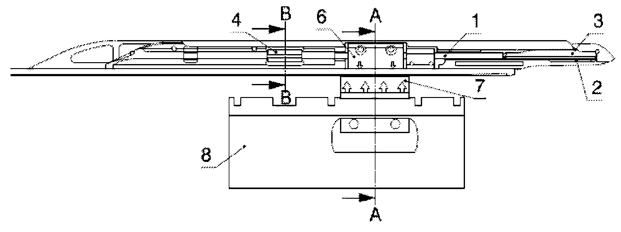
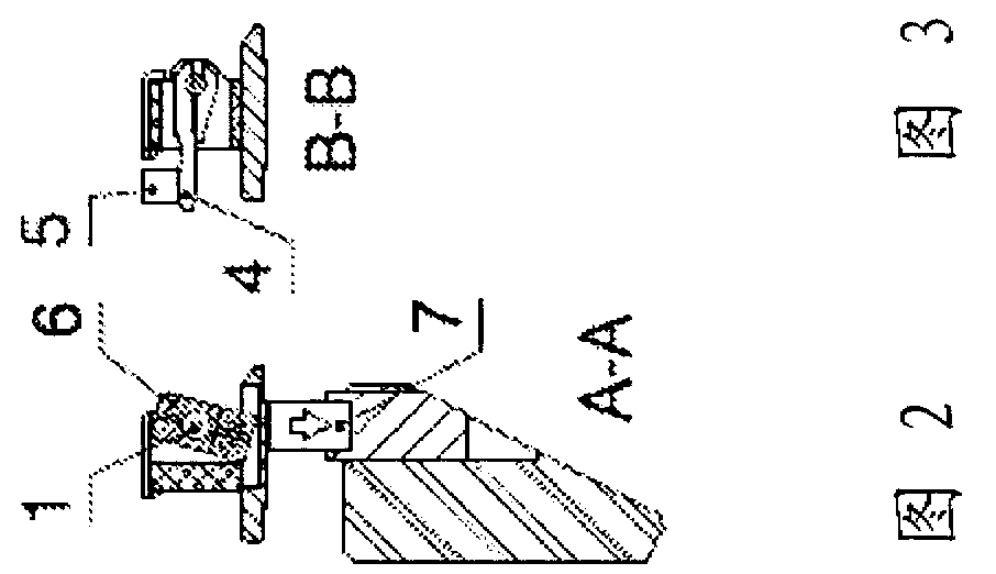
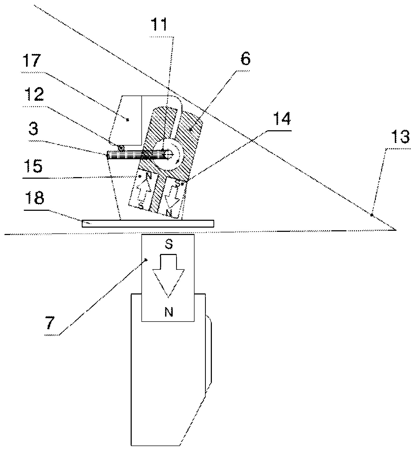
[0020] For a first example of the invention, see Figures 1 to 3 , which show the grippers of this example. The gripper is arranged on a gripper belt or gripper rack 18, guided along a shedway 13, comprising a housing, a gripping part with a gripping tongue 3 and an actuation for manually or mechanically actuating the gripping tongue 3 with 4. The gripper housing is made of plastic. The clamping part is made of metal and is connected with the housing.

[0021] The action of the gripper is based on the Figure 4 The schematic diagram is easy to understand. The torsion shaft 1 is cooperatively connected on one side thereof with an actuation band 4 in a conventional manner. The actuation band 4 abuts against the adapter 5 . The torsion shaft 1 is cooperatively connected on its other side with a pair of permanent magnets 14 and 15 of opposite polarity. In the example, these permanent magnets 14 and 15 are arranged as an extension of a magnet unit 16 configured as an electri...


PUM


Abstract

The gripper has a thread clamp with a continued permanent magnetic device (6) which cooperates with a counter magnet (7) for twisting a torsion bar (1) and release a clamping tongue (3) of a clamping jaw. An actuator (4) is provided for rotating the torsion bar regardless of the permanent magnetic device. The clamping jaw is designed as a fixed jaw.

Description

technical field [0001] The invention relates to a projectile for a projectile weaving machine according to the preamble of claim 1 . Furthermore, the invention relates to a weft thread insertion device with a corresponding gripper. Background technique [0002] In projectile looms, the weft thread is usually inserted into the shed from one side by a bring gripper, and is then transferred, usually about the middle of the shed, to a fetch gripper, which then withdraws the weft thread from the shed . In these two grippers, there is a gripper part formed on the gripper head. The projectile moves along a guide member connected to the reed. [0003] From WO 2000 / 070136A a gripper for inserting weft threads is known, which gripper has a pivotable clamping tongue connected to a rotatable shaft part and clamped by the action of a torsion spring Tight weft. In WO 2000 / 070136A it is proposed to construct the torsion spring as a torsion spring such that one end of the torsion sprin...

Claims


Application Information

Patent Timeline
Patent Type & Authority Applications(China)
IPC IPC(8): D03D47/23
CPCD03D47/23
Inventor D.特朗德尔F.纽豪斯
Owner TEXTILMA AG
Learn More