
Positioning jig device for vehicle body frame

a vehicle body frame and positioning jig technology, which is applied in the direction of forging/hammering/pressing machines, auxilary welding devices, soldering apparatuses, etc., can solve the problems of complex management process for maintaining positional accuracy, increase in facility costs, and troublesome problems, and achieve high-quality positioning of vehicle body frames.

Inactive Publication Date: 2008-12-02
HONDA MOTOR CO LTD
View PDF16 Cites 6 Cited by
  • Summary
  • Abstract
  • Description
  • Claims
  • Application Information

AI Technical Summary

Benefits of technology

[0007]It is an object of the present invention to provide a positioning jig device which is capable of highly accurately positioning a vehicle body frame using a minimum number of required positioning jigs depending upon the types of vehicle body frames only.
[0008]It is another object of the present invention to provide a positioning jig device for a vehicle body frame, which is capable of reducing the cost entailed by positioning jigs.
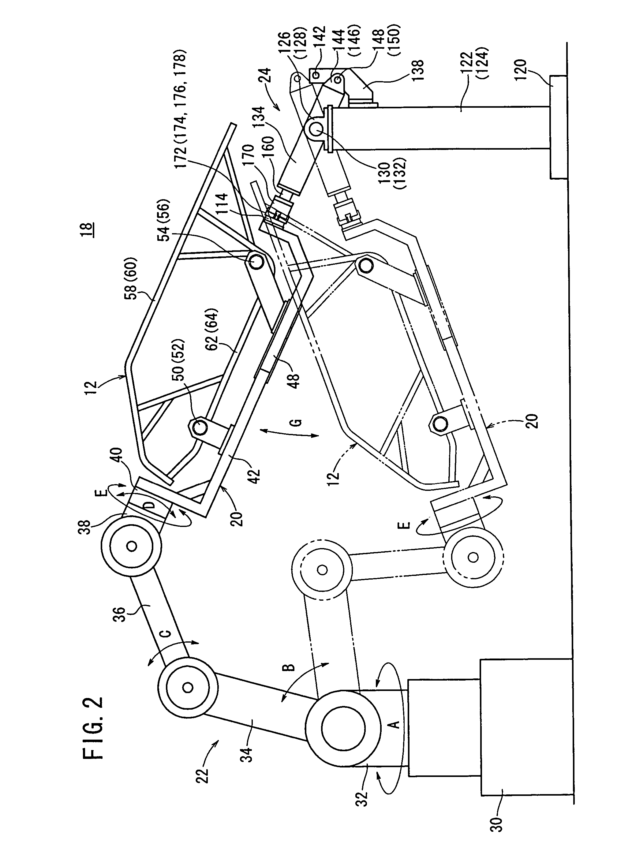
[0009]According to the present invention, a vehicle body frame fixed to a positioning jig which is constructed depending on the form of the vehicle body frame is supplied to a working position by a positioning robot. Then, an engaging member of a positioning jig holder mechanism engages an end of the positioning jig, and the positioning robot positions the vehicle body frame in a desired working attitude. At this time, since the positioning jig is supported by the positioning robot and the positioning jig holder mechanism, the vehicle body frame can stably be worked upon as desired with high accuracy.

Problems solved by technology

As the number of types of vehicle body frames and the number of types of welding robots increase, more types of jigs are required, resulting in an increase in the cost of the facilities.
Furthermore, since the positional relationship between each jig and each welding robot needs to be adjusted once in every two or three months, the management process for maintaining positional accuracy is complicated and troublesome.

Method used


Image

  • Positioning jig device for vehicle body frame
  • Positioning jig device for vehicle body frame
  • Positioning jig device for vehicle body frame

Examples


Embodiment Construction

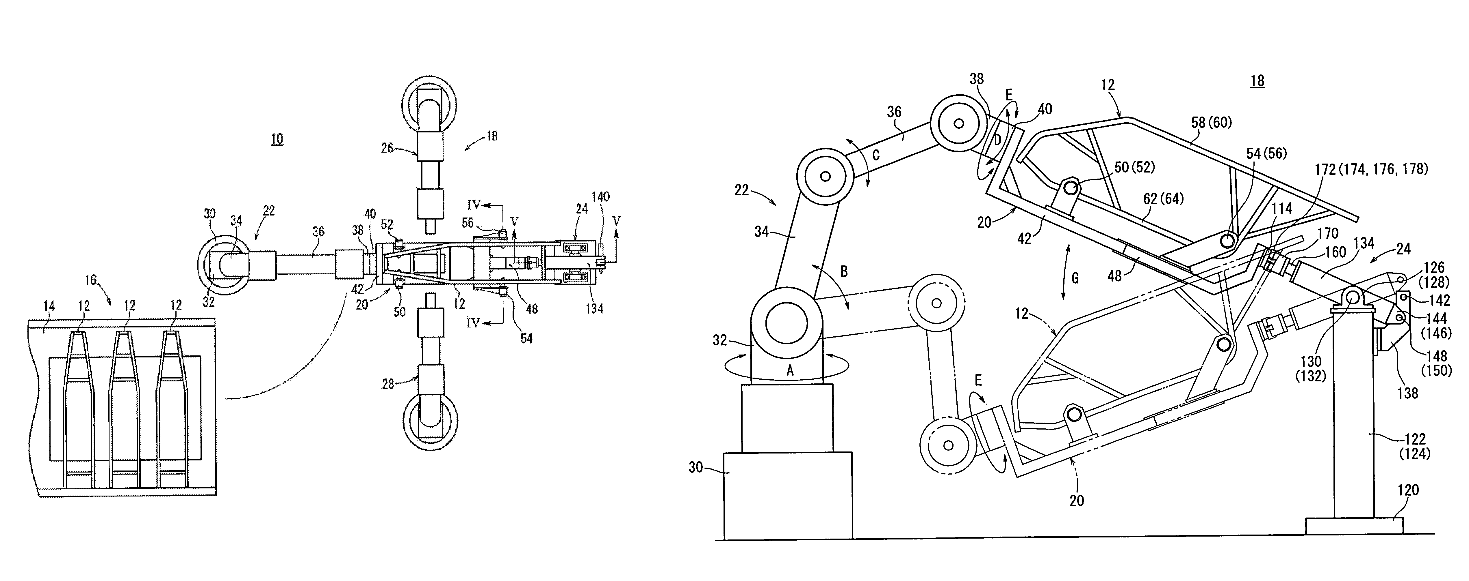
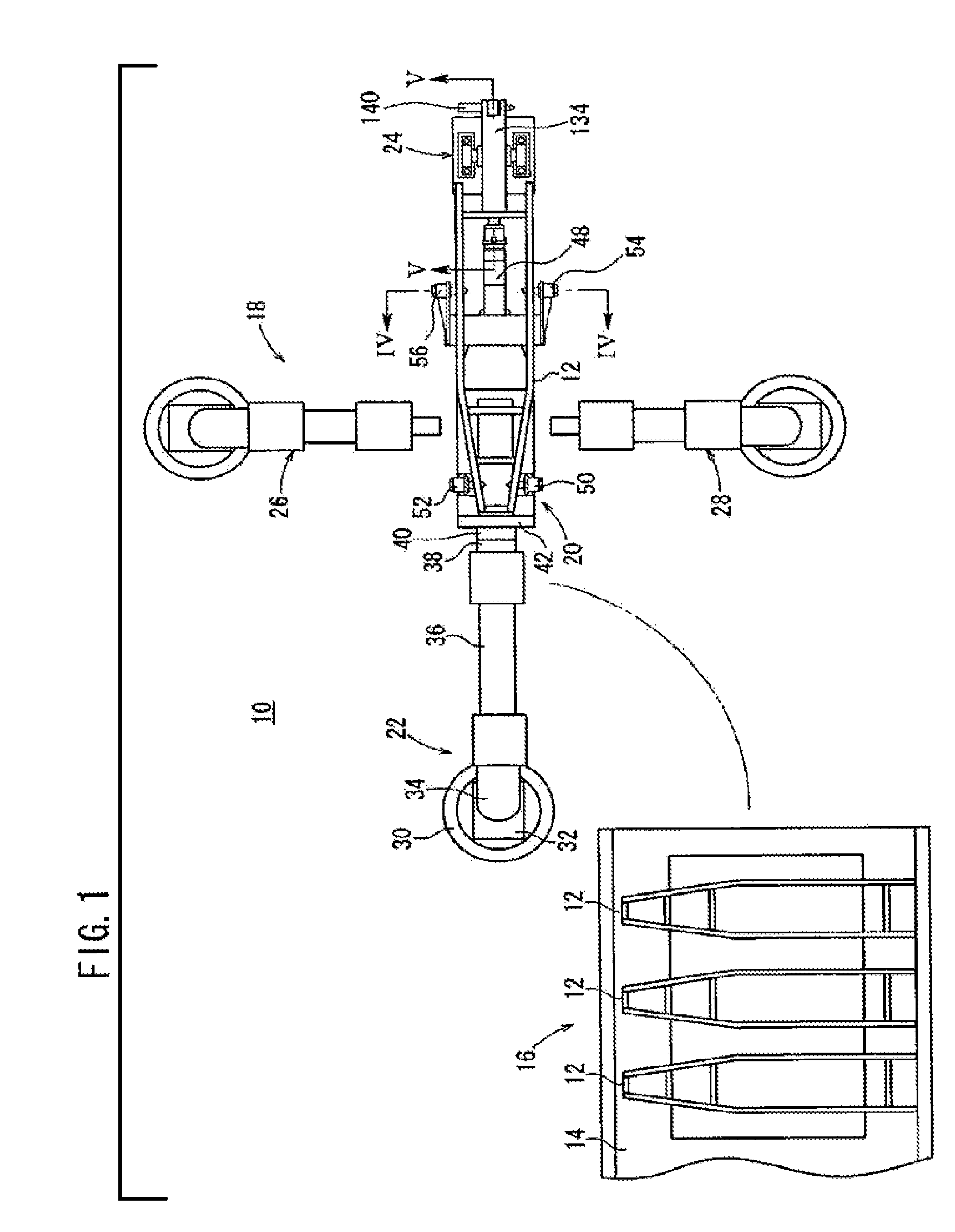
[0017]FIG. 1 is a plan view of a welding system 10 incorporating a positioning jig device for a vehicle body frame according to the present invention.

[0018]The welding system 10 is a system for welding vehicle body frames 12 that are supplied in a temporarily assembled state. The welding system 10 includes a vehicle body frame placement unit 16 having a placement table 14 for placing a plurality of vehicle body frames 12 thereon, a welding station 18 for welding a vehicle body frame 12 supplied from the vehicle body frame placement unit 16, and a positioning robot 22 having a positioning jig 20 for feeding a vehicle body frame 12 from the vehicle body frame placement unit 16 to the welding station 18 and positioning the vehicle body frame 12 in the welding station 18.

[0019]The welding station 18 has a positioning jig holder mechanism 24 for holding the positioning jig 20 in cooperation with the positioning robot 22, and two welding robots 26, 28 for welding the vehicle body frame 12...


PUM

PropertyMeasurementUnit
of rotationaaaaaaaaaa
displacementaaaaaaaaaa
resilientaaaaaaaaaa

Abstract

In a welding station, one end of a positioning jig is held by a positioning robot, and the other end of the positioning jig is held by a positioning jig holder mechanism. The positioning robot is moved for positioning and fixing a vehicle body frame, which is fixed to the positioning jig, in any attitude, and a desired welding operation is performed on the vehicle body frame.

Description

CROSS-REFERENCE TO RELATED APPLICATIONS[0001]The present invention claims priority under 35 USC 119(a)-(d) and 365(b) based on Japanese patent application No. 2003-082134, filed on Mar. 25, 2003. The subject matter of this priority document is incorporated by reference herein.TECHNICAL FIELD[0002]The present invention relates to a positioning jig device for supplying a vehicle body frame to a predetermined working position and positioning and fixing the vehicle body frame.BACKGROUND ART[0003]Heretofore, a welding system for welding vehicle body frames, for example, has a plurality of welding stations with welding robots. Vehicle body frames are positioned on jigs, and are supplied from a workpiece feed path to the respective welding stations where the vehicle body frames are welded.[0004]Jigs for positioning the vehicle body frames in the welding stations are required for each of the various respective vehicle body frames. The positioning relationship between the vehicle body frames...

Claims


Application Information

Patent Timeline
Patent Type & Authority Patents(United States)
IPC IPC(8): B23K37/04B25J9/06B25J9/00B62D65/00B62D65/02
CPCB23K37/0443B25J9/0096B62D65/02
Inventor YAMAOKA, NAOJIMIWA, TEIJI
Owner HONDA MOTOR CO LTD
Learn More