Geometrical optimization of multi-well trajectories

a multi-well, geometric optimization technology, applied in the direction of survey, directional drilling, borehole/well accessories, etc., can solve the problems of long-lasting detrimental effects, locations, and each of the proposed paths may have a cost associated with the production of the well path, and achieve the effect of maximizing profits

Active Publication Date: 2008-12-02
SCHLUMBERGER TECH CORP
View PDF10 Cites 89 Cited by
  • Summary
  • Abstract
  • Description
  • Claims
  • Application Information

AI Technical Summary

Benefits of technology

[0008]In an alternative embodiment, well production values need not be assigned to each well-target location. Instead of maximizing the total project value, the optimizer minimizes total project cost, where project costs include the various costs of drilling, platform location and building.
[0011]In an example of the present embodiment, the specification of a plurality of well targets may be based upon derived seismic data. In an embodiment, this specification of a number of targets may be based on recorded seismic data. Additionally, the association of a target value with each of these well-target locations may be based on numerous factors, including well simulation data, surface and sub-surface production constraint data, geohazard data or user defined factors. In accordance with the present embodiment, the generation of one or more well paths may further include the identification of the lowest cost optimized well path. This lowest-cost optimized well path may be viewed as the most beneficial well path for maximizing profits.

Problems solved by technology

Each of these proposed pathways have a cost associated with the production of the well path, as well as a degree of difficulty that may be influenced by various factors such as topography or earth composition.
Additionally, sub-optimal selection of well pathways, platform locations, or the total number of wells may have long lasting detrimental effects.
To date this is a highly unpredictable method of platform location, as the generated data set on which long term decisions is based is unnecessarily small.
Furthermore, such a computational approach is processor intensive, and may take a long period of time for results to be generated.

Method used


Image

  • Geometrical optimization of multi-well trajectories
  • Geometrical optimization of multi-well trajectories
  • Geometrical optimization of multi-well trajectories

Examples


Embodiment Construction

[0025]Various embodiments and aspects of the invention will now be described in detail with reference to the accompanying figures. This invention is not limited in its application to the details of construction and the arrangement of components set forth in the following description or illustrated in the drawings. The invention is capable of various alternative embodiments and may be practiced using a variety of other ways. Furthermore, the terminology and phraseology used herein is solely used for descriptive purposes and should not be construed as limiting in scope. Language such as “including,”“comprising,”“having,”“containing,” or “involving,” and variations herein, are intended to encompass both the items listed thereafter, equivalents, and additional items not recited.

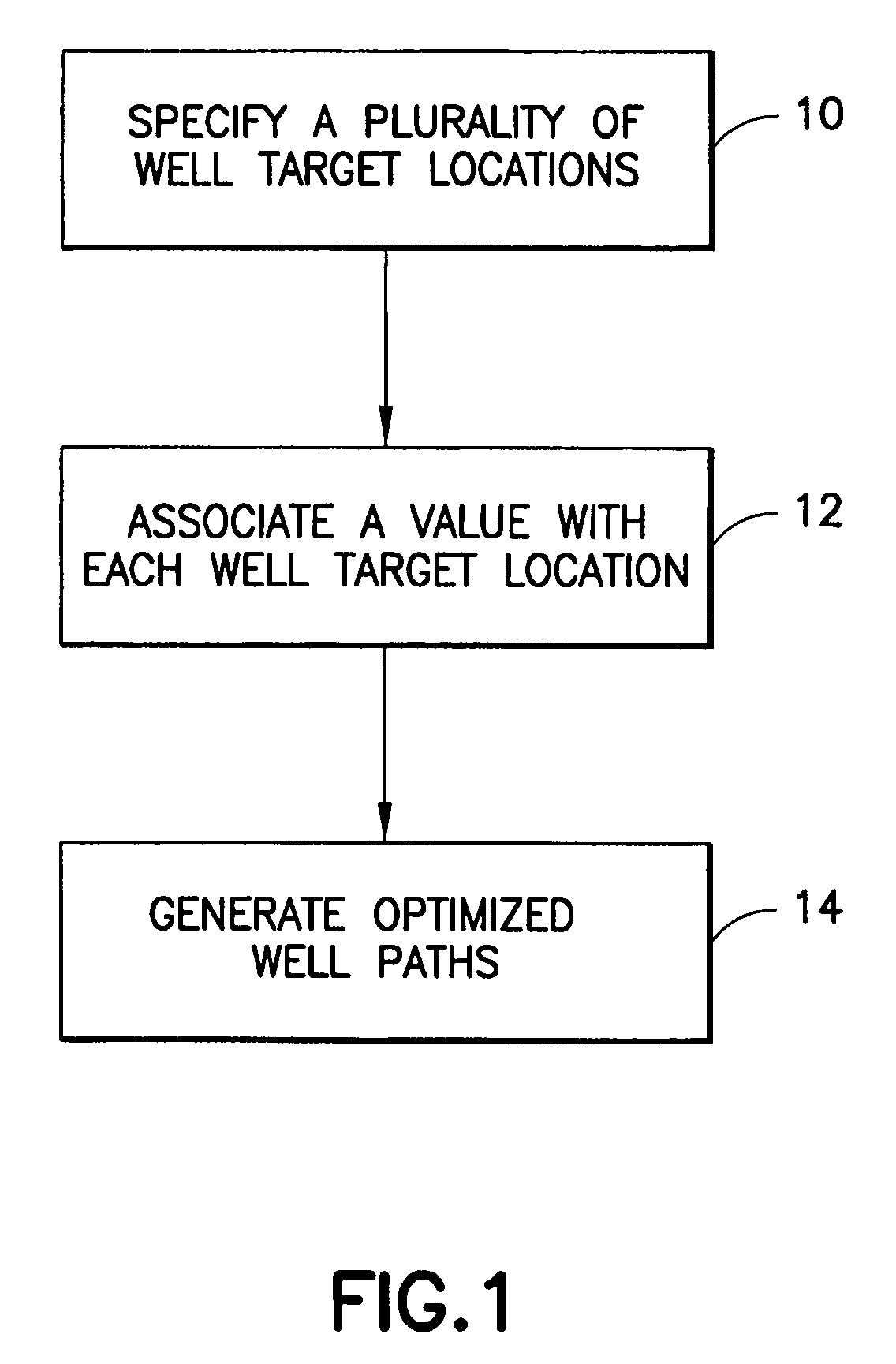
[0026]As illustrated in FIG. 1, a flowchart illustrating the steps necessary in practicing an embodiment of the present invention is recited. In accordance with step 10 a plurality of well-target locations are fi...


PUM


Abstract

A novel method is presented to automatically design a multi-well development plan given a set of previously interpreted subsurface targets. This method identifies the optimal plan by minimizing the total cost as a function of existing and required new platforms, the number of wells, and the drilling cost of each of the wells. The cost of each well is a function of the well path and the overall complexity of the well.

Description

CROSS REFERENCE TO RELATED APPLICATIONS[0001]This invention claims priority from U.S. Provisional Application No. 60 / 636,076 filed on Dec. 14, 2004.FIELD OF THE INVENTION [0002]The present invention relates to a method, system and apparatus for automatically designing a well development plan, and more particularly on the determination of an optimum plan by minimizing the total cost as a function of existing and required new platforms, the number of wells, and the drilling cost of each of the wells.BACKGROUND OF THE INVENTION [0003]Seismic and well log data is traditionally used to define and estimate the subsurface structure of reservoir bodies or target sites. Seismic and well log data can provide porosity, permeability, fluid and gas saturation data, as well as other reservoir properties, which is measured and computed at a high level of accuracy. These data are often plotted using a computer simulation such that the regions of interest are defined relative to various features, su...

Claims


Application Information

Patent Timeline
Patent Type & Authority Patents(United States)
IPC IPC(8): G01V1/40G06G7/48
CPCE21B7/04E21B43/305E21B47/022E21B41/00
Inventor PRANGE, MICHAEL DAVIDTILKE, PETER GERHARDCHAPMAN, CLINTON DANEAKLESTAD, DARREN LEE
Owner SCHLUMBERGER TECH CORP
Why Eureka
Try Eureka