Drive device comprising a gearbox

a technology of a gearbox and a drive device, which is applied in the direction of gearboxes, instruments, mechanical equipment, etc., can solve the problems of reducing the current revolution speed difference, affecting the operation of the gearbox, and the clutch is not comfortable, so as to reduce the tractive force, the main engine torque is advantageously reduced, and the time span is clearly lessened

Inactive Publication Date: 2008-12-09
ZF FRIEDRICHSHAFEN AG
View PDF17 Cites 3 Cited by
  • Summary
  • Abstract
  • Description
  • Claims
  • Application Information

AI Technical Summary

Benefits of technology

[0010]This has the advantage that through the interplay of the shifting clutch and the shifting brake clutch, the decrease in tractive force, typically due to the opening phase of the shifting clutch, is connected via the active connection of the shifting brake clutch with the gear output, i.e., the main engine torque supports itself in this phase in the transmission output. With a gear change, the two clutches operate in an intersecting manner whereby the main engine torque is advantageously reduced through the torque support to a transferable degree by the shifting brake clutch.
[0011]With a gearshift up to the next higher gear, a sinking of the main engine revolution speed is thus successfully achieved by that amount, which ensues from the revolution speed change of the gear change, under simultaneous support of the torque in the transmission output. With the drive device, according to the invention, both the complete collapse of the tractive force transmission occurring typically in the drive devices, according to the state of the art, is thus prevented and the time span is clearly lessened with reduced tractive force.

Problems solved by technology

Since the shifting clutch is opened with synchronized transmissions with shifting operations between the main engine and transmission generally, and with unsynchronized transmissions with an upward gearshift, with the achieved shortening of the tractive force interruption, thus the shortening of the time span for the mechanical gear change, the problem increasingly arises of reducing the currently existing revolution speed difference at the conclusion of the gear change via the shifting clutch without losses in comfort as well as at the same time wear resistant clashing with the clutch and main engine torque.
These measures, however, run contrary to the already achieved shortening of the time for the mechanical gear change.

Method used


Image

  • Drive device comprising a gearbox
  • Drive device comprising a gearbox
  • Drive device comprising a gearbox

Examples


Embodiment Construction

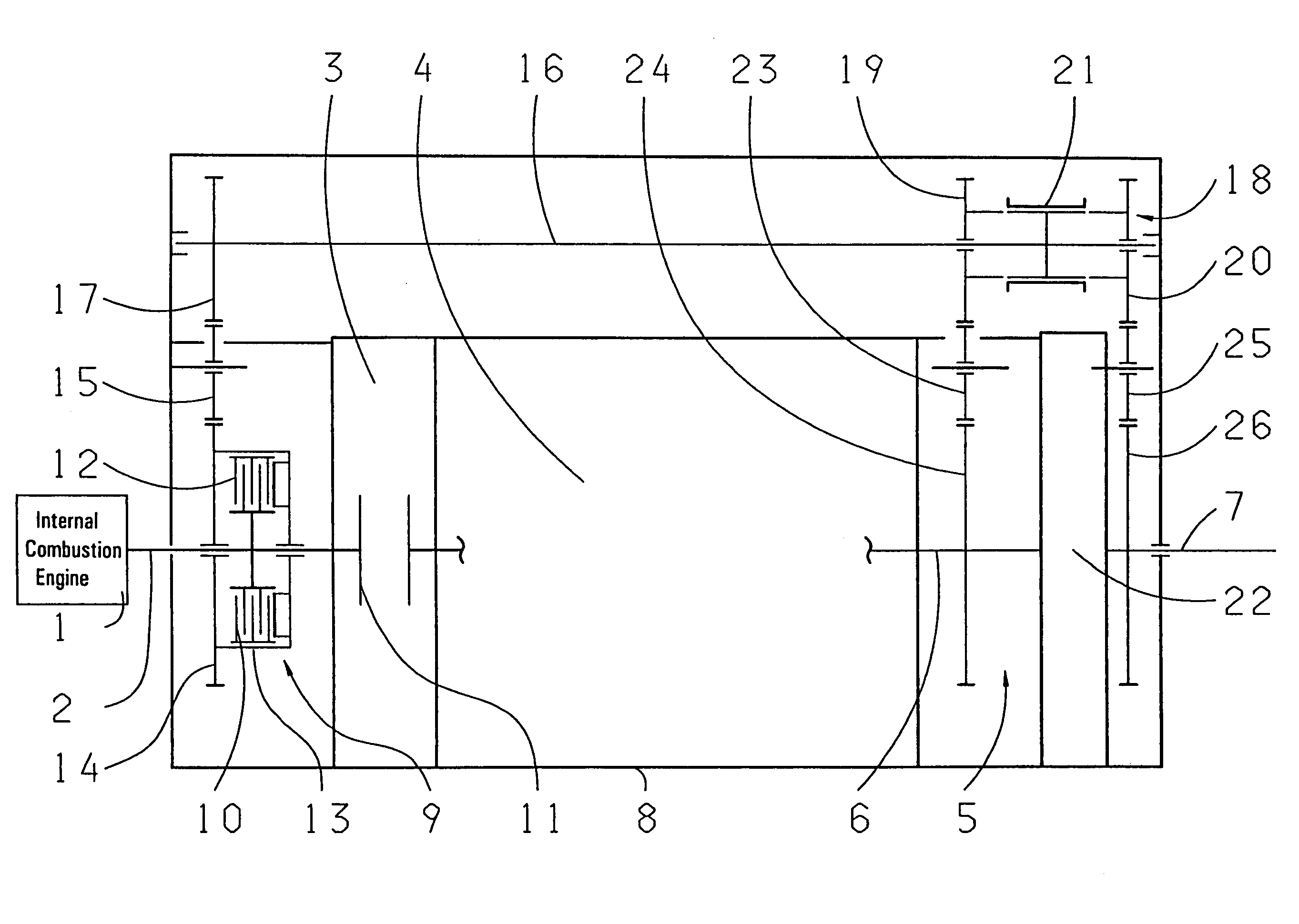
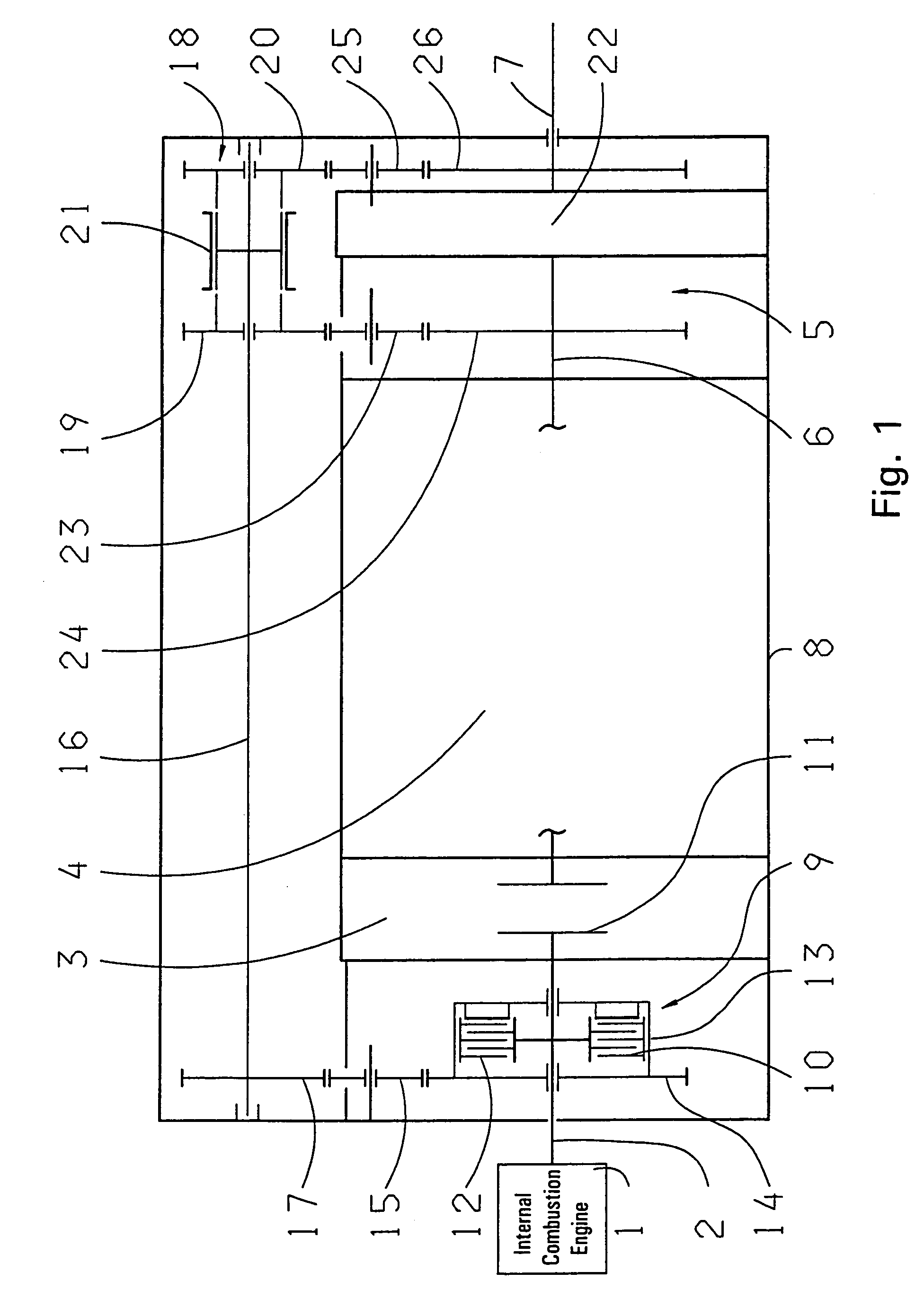
[0023]In FIG. 1, a main engine is discernible and designed as an internal combustion engine 1, which relays its torque by way of a drive shaft 2 on the input side of a shifting clutch 3. This, in turn, is assigned to a transmission 4 or also a main gear drive, which shows a known construction and thus not shown in more detail here. Such a transmission can also be designed as an automated transmission. A gear output 5, in addition, shows a gear output shaft 6 and a main output shaft 7.

[0024]These specified units are structurally unified inside a housing 8 with the exception of the internal combustion engine 1. Between the drive shaft 2 and the shifting clutch 3, serving also as a start-up clutch, a shifting brake clutch 9 is arranged, whereby the drive shaft 2 permanently drives a radial inner disk pact 10 of the shifting brake clutch 9. The drive shaft 2 is executed axially by the shifting brake clutch 9 and acts permanently on an input-sided clutch surface 11 of the shifting clutch...


PUM


Abstract

A drive device for a transmission (4), a main engine and a shifting clutch (3). In order to reduce the phase of tractive force interruption during switching operations, the drive device has a shifting brake clutch (9), located between the engine and the shifting clutch, such that during switching operations, intersecting disengaging and engaging processes of both clutches (3 or 9), provide for support of the main engine torque in a gear output (5).

Description

[0001]This application is a national stage completion of PCT / EP2004 / 014204 filed Dec. 14, 2004 which claims priority from German Application Ser. No. 10 2004 002 283.6 filed Jan. 16, 2004.FIELD OF THE INVENTION[0002]The invention concerns a drive device with a transmission.BACKGROUND OF THE INVENTION[0003]Drive devices with a transmission and, for example, a main engine designed as an internal combustion engine, are generally known in vehicle construction. With such drive devices, the main engine is actively connected with a drive shaft which, on its part, starts the input side of a shifting clutch assigned to the transmission. The output of this shifting clutch is then connected drive-technically with the input shaft of the transmission, whose output acts upon the vehicle wheels being propelled via a differential gear.[0004]As a rule, such transmissions are designed as multi-step transmissions with whose operation it comes to a tractive force interruption with the gear change, whic...

Claims


Application Information

Patent Timeline
Patent Type & Authority Patents(United States)
IPC IPC(8): F16H3/08F16H61/04
CPCF16H3/12F16H61/0403F16H37/046Y10T74/19233F16H2061/0411F16H2061/0425F16H2061/0429F16H2061/0407
Inventor DOBELE, BERND
Owner ZF FRIEDRICHSHAFEN AG
Why Eureka
Try Eureka