
Rotary-actuated exhaust gas recirculation valve having a seating force attenuator

a technology of exhaust gas recirculation valve and seat force, which is applied in the direction of valve operating means/release devices, machines/engines, non-mechanical valves, etc., can solve the problems of valve seat wear, valve stem degradation, and force on the valve actuation train

Inactive Publication Date: 2008-12-09
DELPHI TECH INC
View PDF6 Cites 17 Cited by
  • Summary
  • Abstract
  • Description
  • Claims
  • Application Information

AI Technical Summary

Problems solved by technology

A disadvantage of such actuation is inherently high and sustained forces imposed on the valve actuation train that can prove detrimental for long-term wear, including grooving of the valve head, wear of the valve seat, and degradation of the interface between the cam and its roller follower on the valve stem.
Such wear can result in high break-loose forces and “kinking”, leading to poor controllability in the just off-parked position.

Method used


Image

  • Rotary-actuated exhaust gas recirculation valve having a seating force attenuator
  • Rotary-actuated exhaust gas recirculation valve having a seating force attenuator
  • Rotary-actuated exhaust gas recirculation valve having a seating force attenuator

Examples


Embodiment Construction

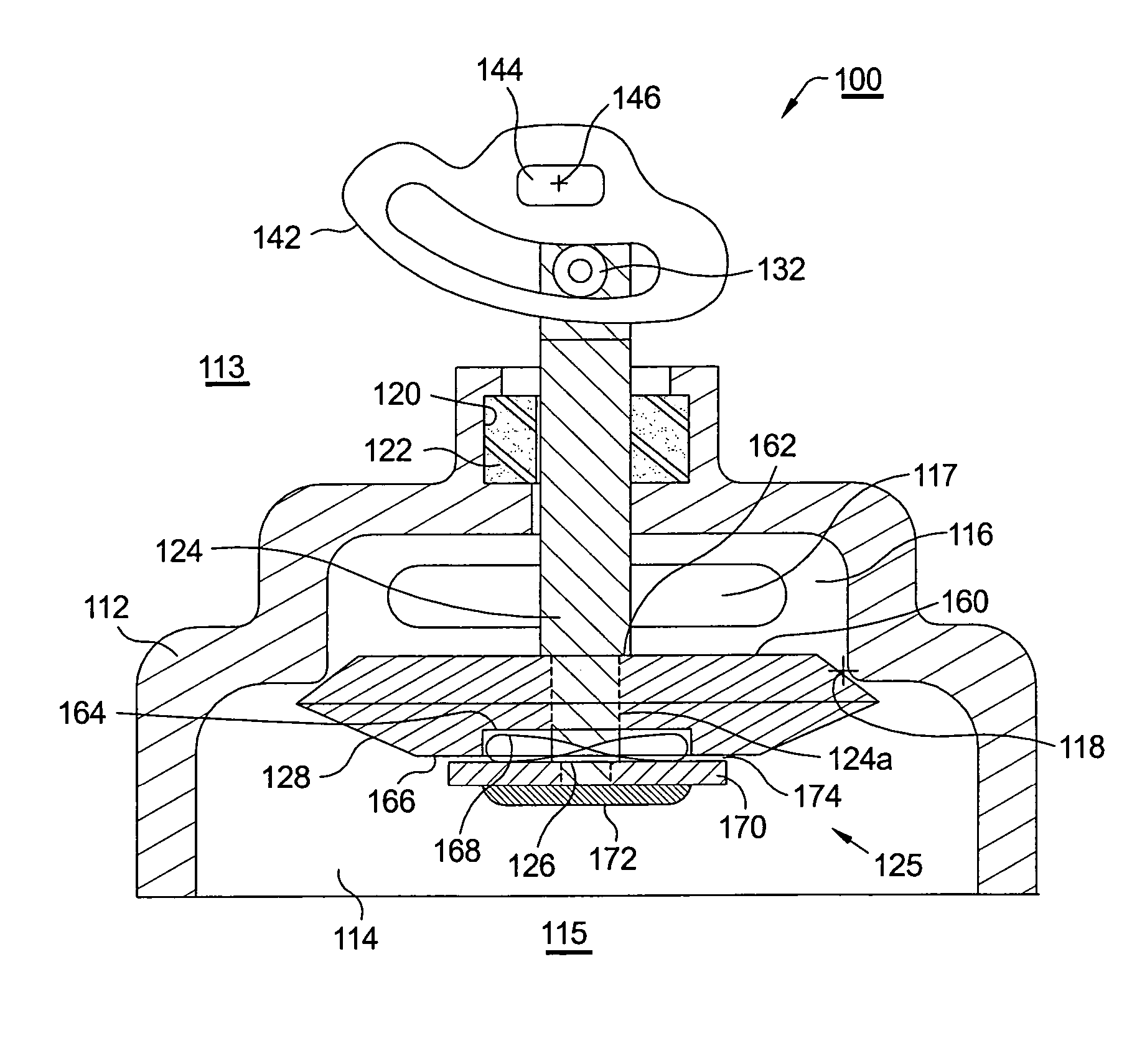
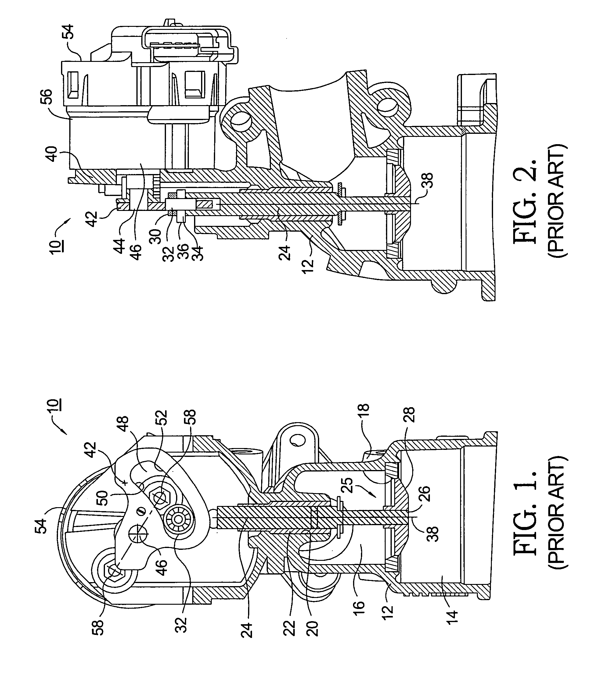
[0016]Referring to FIGS. 1 and 2, a prior art poppet valve assembly 10 suitable for use as an EGR valve comprises a valve body 12 defining a first chamber 14 and a second chamber 16 separated by a valve seat 18. A bore 20 in a wall of second chamber 16 is concentric with valve seat 18 and retains a bushing / seal 22 and a valve stem 24 of a poppet valve 25 slidably disposed in bushing / seal 22. Stem 24 extends through second chamber 16 and fixedly supports, at a first end 26 within body 12, a valve head 28 for variably mating with valve seat 18 to variably open and close valve 10 between chambers 14,16 in response to axial motion of stem 24. At a second stem end 30 outside of body 12, stem 24 is provided with a roller 32 mounted on a first shaft34 extending from stem 24 and having an axis 36 orthogonal to axis 38 of stem 24. A bracket 40 extending from body 12 supports a cam plate 42 mounted on a second shaft 44 extending from bracket 40 and also having an axis 46 orthogonal to, but pr...


PUM


Abstract

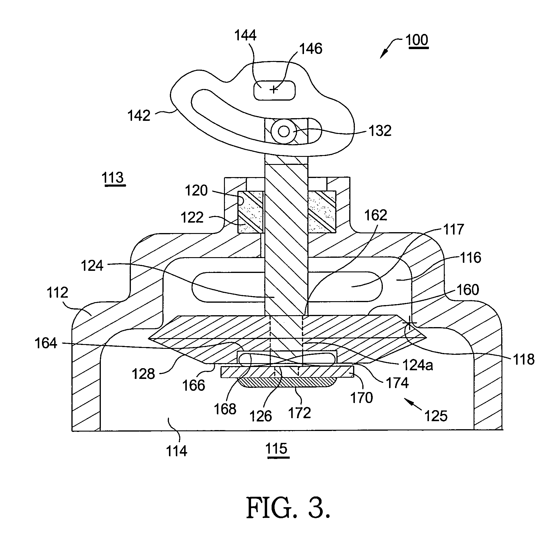
Means for attenuating the seating force of a cam-actuated poppet valve such as an exhaust gas recirculation valve in an internal combustion engine including a shock-absorber disposed between the valve stem and valve head. In a currently preferred embodiment, the shock-absorber is a wave washer disposed around the valve stem and captured between the valve stem and the valve head, between which axial motion is allowed. After the valve head engages the valve seat to close the valve, any further travel of the actuator cam and valve stem is absorbed by compression of the wave washer, thus attenuating additional force on elements of the valve actuation train. In opening the valve, the reverse occurs, in that initial motion of the actuator cam and valve stem serves to relieve compression of the wave washer, followed by removal of the valve head from the valve seat.

Description

TECHNICAL FIELD[0001]The present invention relates to exhaust gas recirculation (EGR) valves for internal combustion engines; more particularly, to EGR valves having a poppet valve stem actuated by a rotary cam; and most particularly, to such an EGR valve wherein the valve seating force between the valve head and the valve seat is attenuated by a mechanical shock-absorbing mechanism disposed between the valve stem and the valve head.BACKGROUND OF THE INVENTION[0002]Recirculation of exhaust gas into the air intake stream of an internal combustion engine is well known, both for spark-ignited (SI) engines and for compression-ignited (CI) engines. Such recirculation requires a rugged, dependable, precision valve, typically a poppet valve, disposed in a cross-over between an engine's exhaust system and intake system. In many prior art automotive uses, an EGR poppet valve is actuated by a linear solenoid attached to the valve stem. However, a rotary cam driven by an electric motor is also...

Claims


Application Information

Patent Timeline
Patent Type & Authority Patents(United States)
IPC IPC(8): F02M25/07F01L1/30F16K1/32F02B47/08
CPCF02M25/0789F02M25/079F01L1/30F01L2009/0411F01L2105/00F02M25/0773Y02T10/121F02M26/54F02M26/67F02M26/68F01L2305/00F01L9/22
Inventor BIRCANN, RAUL A.HAINES, JOSHUA M.
Owner DELPHI TECH INC
Learn More