Post hole digger

a digger and post technology, applied in the field of post diggers, can solve the problems of unfavorable workers, unfavorable workers, and unfavorable workers, and achieve the effects of reducing labor intensity, reducing labor intensity, and reducing the number of workers

Active Publication Date: 2008-12-09
IAMS
View PDF29 Cites 13 Cited by
  • Summary
  • Abstract
  • Description
  • Claims
  • Application Information

AI Technical Summary

Benefits of technology

[0013]These needs, and others, are met by at least one embodiment of this invention which provides a post hole digger having a first, traverse pivot point, located on the medial portions of two handle members, and a second, blade assembly pivot point located at the medial point of the blade assemblies. Because the first pivot point is a traverse pivot point, the handles are only required to travel through a limited range of motion. Additionally, the second blade assembly pivot point is preferably an offset pivot point. Thus, because the second, blade assembly pivot point is disposed at a medial point of the blade assemblies, the motion of the handle members, which are coupled to the upper ends of the blade assemblies, is reversed relative to the lower ends of the blade members. In this configuration, the handle member's first position, which corresponds to the blade assembly open position, is in the preferred generally vertical and parallel orientation. Further, once the post hole digger has engaged the ground, a worker uses the preferred pulling apart motion on the handles to move the blade assembly into the second, closed position. Additionally, the post hole digger may utilize a hand ledge disposed at the upper end of each handle as a stop member. That is, each hand ledge extends toward the opposite handle and is sized to abut the opposing hand ledge when the handles are generally parallel to each other. Thus, a worker does not have to manually maintain the position of the handle members as with the prior art traverse pivot point post hole diggers. As an added advantage, the hand ledges also help to resist the workers hands slipping upwardly on the handles when the worker lifts the post hole digger out of the hole.

Problems solved by technology

However, the handles may not be too long as the tool could be too heavy to lift repeatedly and / or too unwieldy to use comfortably.
Lengthening the blades would reduce the amount of travel required to close the blades, but would, in turn, reduce the relative lever arm between the blades and the handles, thus requiring a greater effort on the part of the worker.
An offset pivot post hole digger according to this configuration is easy to manufacture and is not too heavy; however, the range of motion of the handles is not suitable for a moderately deep hole.
As such, some workers do not care for a traverse pivot point post hole digger.
This configuration also has a disadvantage in that, when thrusting the tool downwardly, the worker must hold the handles 1A, 2A within a generally narrow range of separation in order for the blades 3A, 4A to be maintained generally perpendicular to the ground during the bite.
Moreover, the worker's hands may be in an awkward position during the thrust.

Method used


Image

  • Post hole digger
  • Post hole digger
  • Post hole digger

Examples


Embodiment Construction

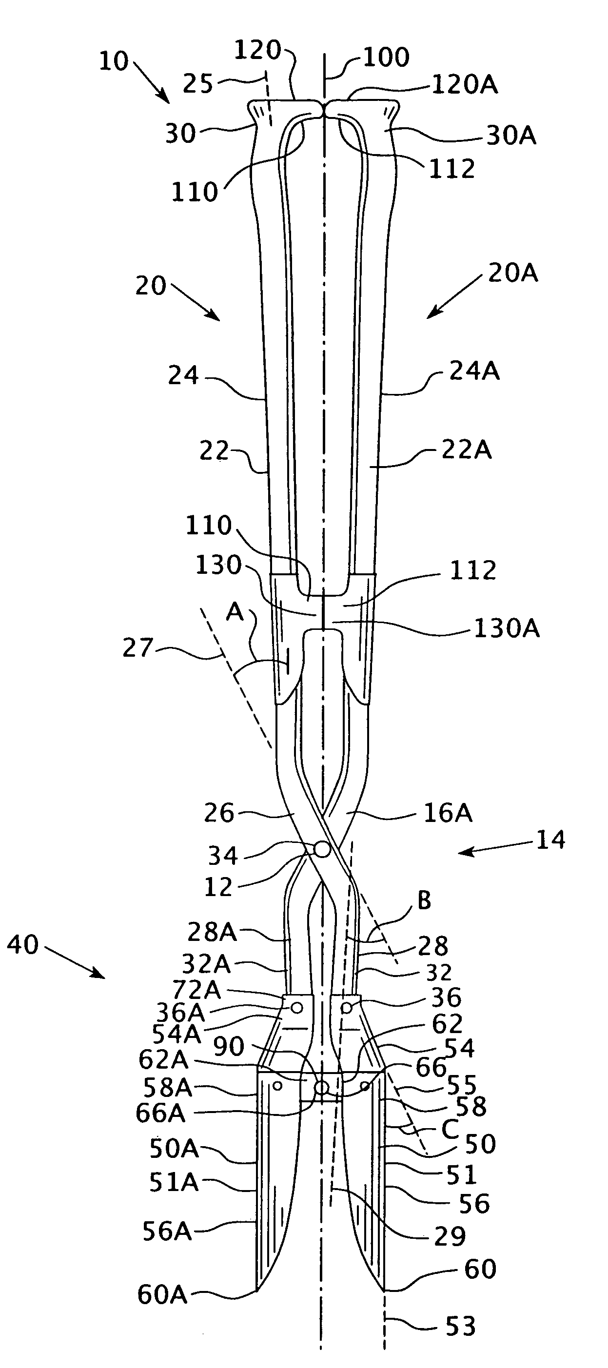
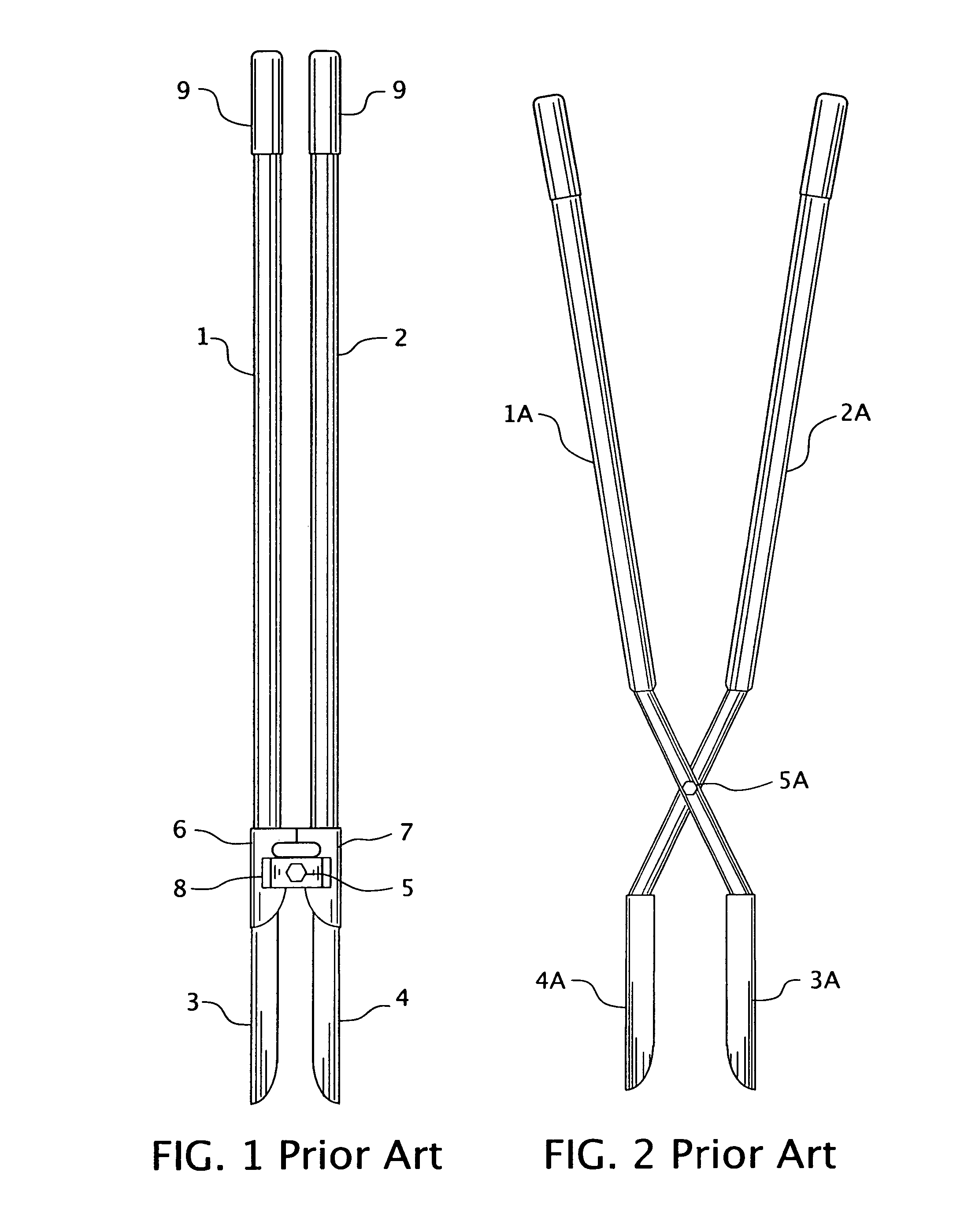
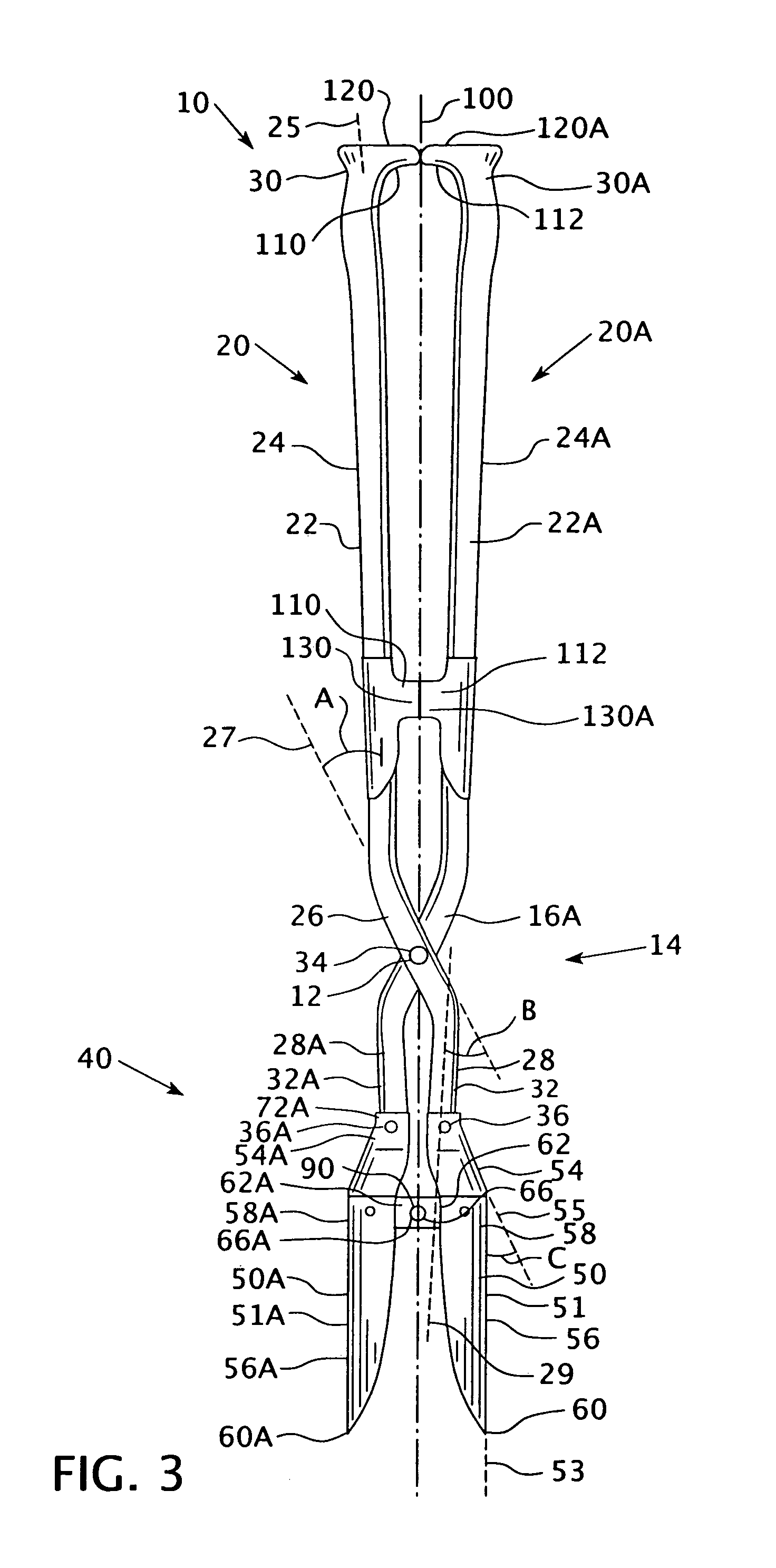
[0020]As used herein an “offset pivot point” shall mean a configuration wherein each handle and associated blade may be, and generally are, disposed on the same side of the pivot point, the pivot point being located on one or more structures extending toward the opposing handle / blade.

[0021]As used herein a “traverse pivot point” shall mean a scissor-like configuration wherein two members cross over each other with the pivot point extending through the point of intersection.

[0022]As used herein, “coupled” means a link between two or more elements, whether direct or indirect, so long as a link occurs.

[0023]As used herein, “directly coupled” means that two elements are directly in contact with each other.

[0024]As used herein directional words, such as, but not limited to, “upper” and “lower” shall be used in relation to the Figures and are not limiting upon the claims.

[0025]As shown in FIGS. 3 and 4, a post hole digger 10 includes a first handle assembly 20, a second handle assembly 20...


PUM


Abstract

This invention provides a post hole digger having a first, traverse pivot point, located on the medial portions of two handle members, and a second, blade assembly pivot point located at the medial point of the blade assemblies. Because the first pivot point is a traverse pivot point, the handle members are only required to travel through a limited range of motion. Additionally, the second, blade assembly pivot point is preferably an offset pivot point. Thus, because the second, blade assembly pivot point is disposed at a medial point of the blade assemblies, the motion of the handle members, which are coupled to the upper ends of the blade assemblies, is reversed relative to the lower ends of the blade members.

Description

BACKGROUND OF THE INVENTION[0001]1. Field of the Invention[0002]This invention relates to a post hole digger and, more specifically, to a post hole digger having a traverse pivot point coupling two handle assemblies to each other, a blade assembly having two blade members, each blade member pivotally coupled to one handle assembly, and an offset pivot point coupling the two blade members to each other.[0003]2. Background Information[0004]A post hole digger is structured to dig a hole having a generally narrow cross-sectional area relative to the depth of the hole. The hole was typically dug in a compacted particulate or granulated material, hereinafter “the ground.” The material removed from the hole shall be referred to as “the dirt.” The dirt was, typically, a loose granulate material. Preferably, the post hole had a greater cross-sectional area that a post that was inserted therein. A portion of the loose dirt, or another material such as concrete, was then reinserted into the an...

Claims


Application Information

Patent Timeline
Patent Type & Authority Patents(United States)
IPC IPC(8): A01B1/00
CPCE21B11/005G02B6/122G02B2006/1204
Inventor NORTON, JEFFREY M.ALBERT, BARRY R.
Owner IAMS
Why Eureka
Try Eureka