Battered column tension leg platform

a technology of tension leg and plate, which is applied in the direction of special-purpose vessels, vessel construction, transportation and packaging, etc., can solve the problems of hydrostatic stability of tlp, and achieve the effect of contributing to platform stability

Inactive Publication Date: 2008-12-09
SEAHORSE EQUIP
View PDF12 Cites 29 Cited by
  • Summary
  • Abstract
  • Description
  • Claims
  • Application Information

AI Technical Summary

Benefits of technology

[0005]In accordance with a preferred embodiment of the present invention, a tension leg platform includes a deck supported on the upper ends of at least three columns interconnected at the lower ends thereof by horizontally disposed pontoons. The columns are battered inwardly from the pontoons to the deck. Tendons connected at porches extending outwardly from the lower ends of the columns anchor the platform to the seabed. The footprint of the tendons is substantially the same or slightly larger than the footprint of the battered columns, whereas the footprint of the deck is smaller than the footprint of the columns. The battered columns also contribute to platform stability during free floating operations by providing a large water plane dimension at shallow draft.

Problems solved by technology

In such conventional TLP designs, the footprints of the deck, the vertical columns and the tendons are substantially the same and therefore hydrostatic stability of the TLP can be a problem.

Method used


Image

  • Battered column tension leg platform
  • Battered column tension leg platform
  • Battered column tension leg platform

Examples


Embodiment Construction

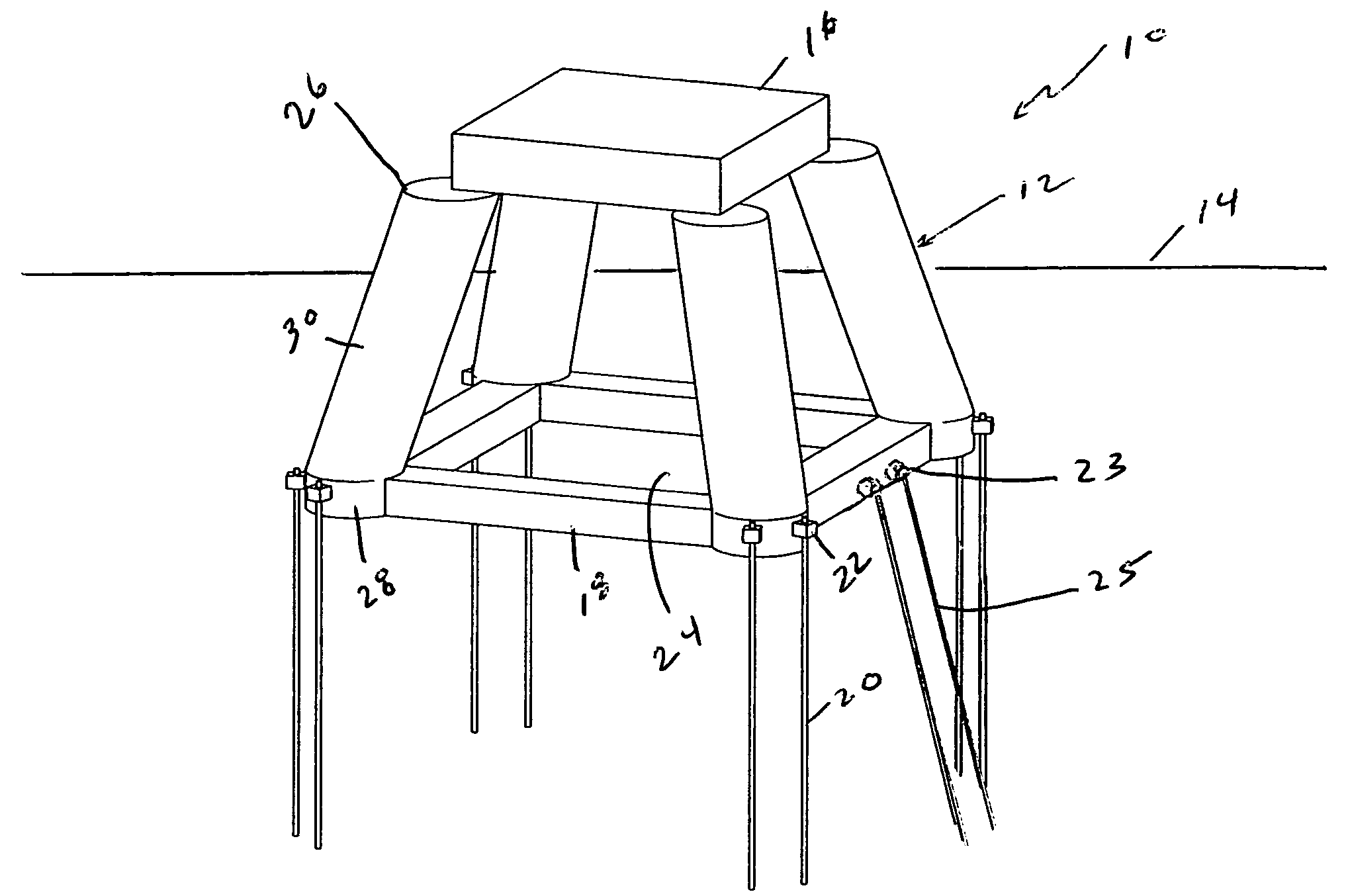
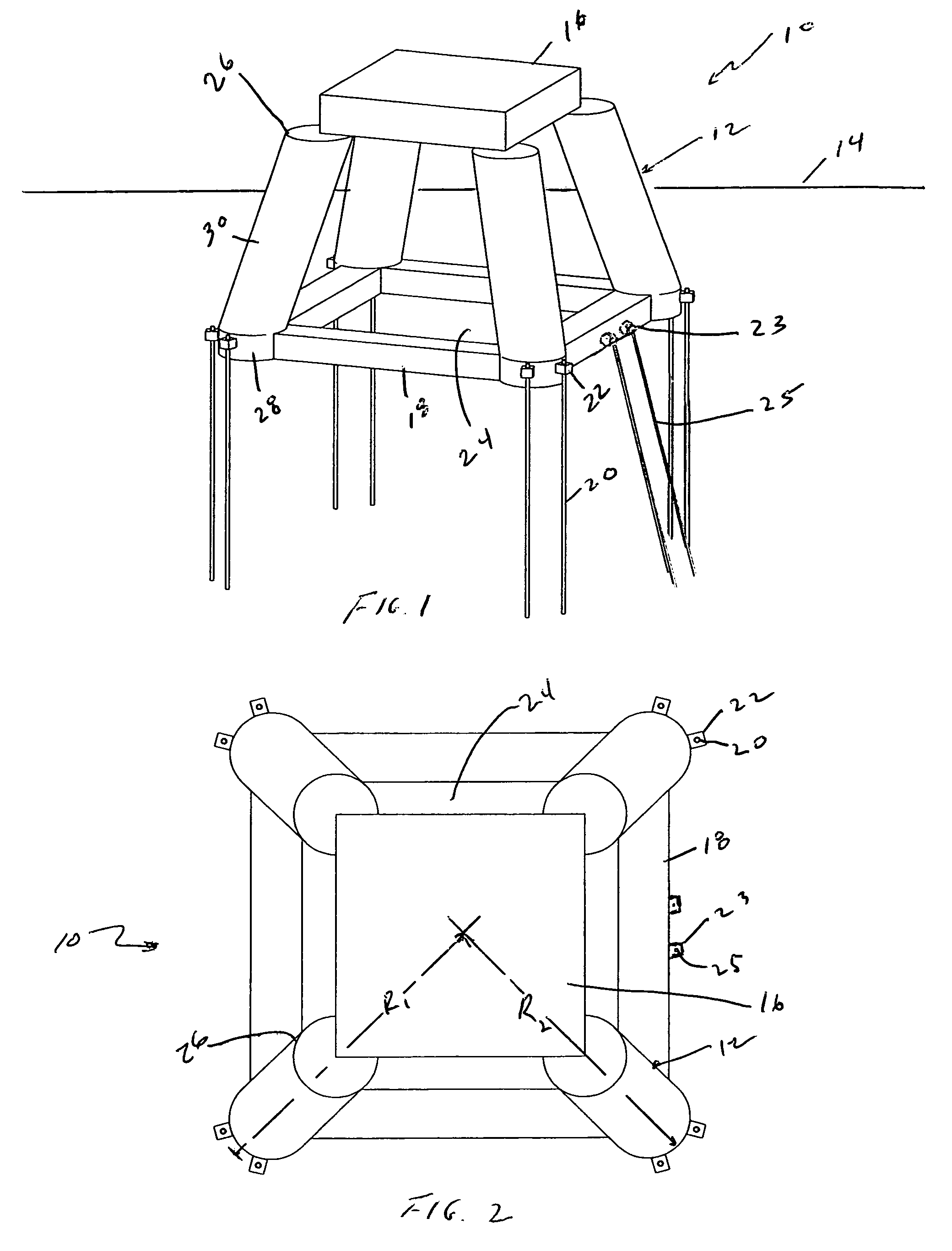
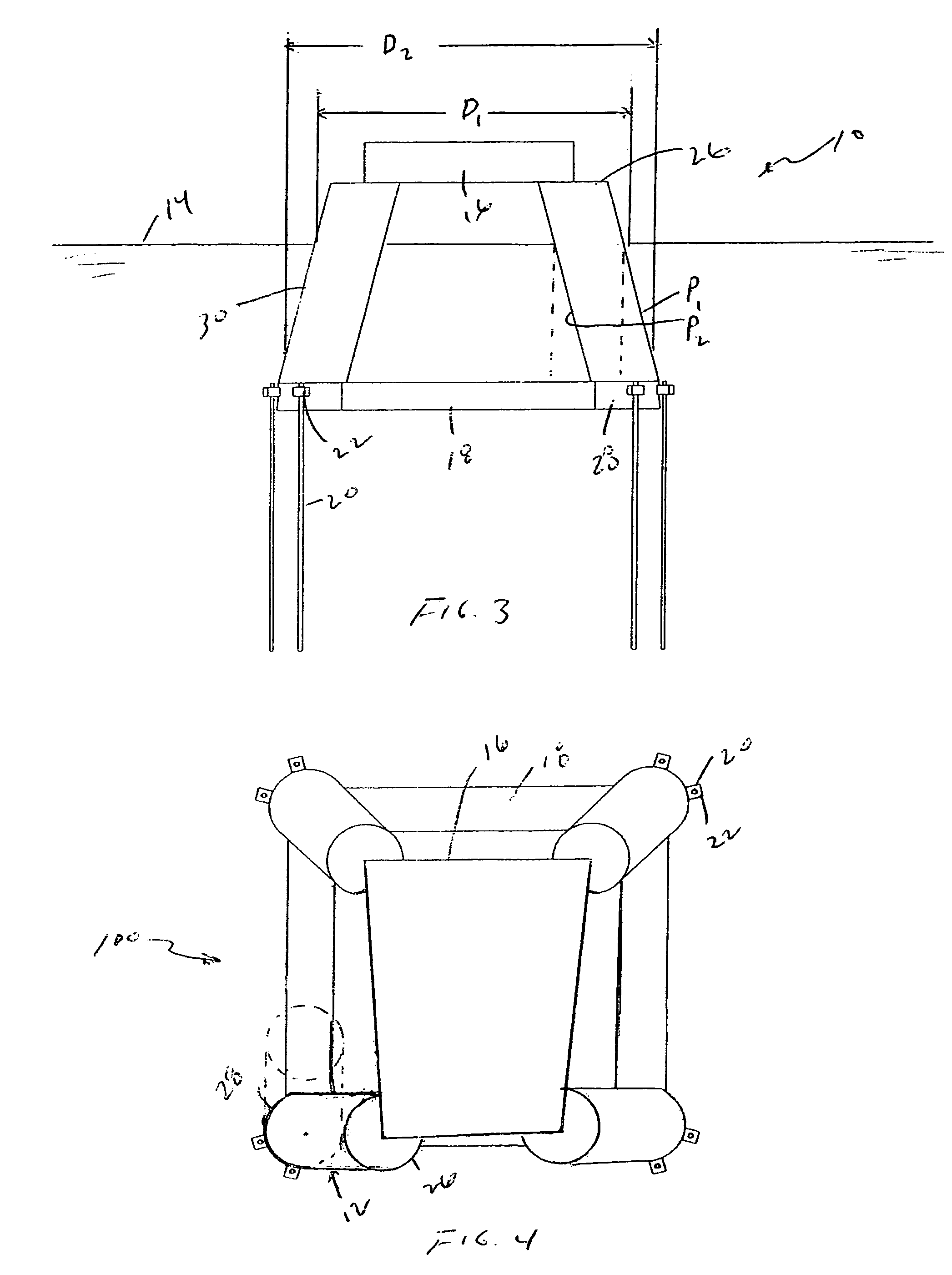
[0016]Referring first to FIG. 1, a preferred embodiment of a TLP system in accordance with the present invention is generally identified by the reference numeral 10. The TLP 10 includes four columns 12 having upper ends projecting above the water surface 14 for engaging and supporting a platform deck 16 thereon. Horizontally disposed pontoons 18 interconnect adjacent columns 12 proximate the lower ends thereof. The TLP 10 is anchored to the seabed by tendons 20. The upper ends of one, two or more tendons 20 are connected at each column 12 and the lower ends thereof are anchored to the seabed. Tendon porches 22 mounted proximate to and outboard of the lower ends of the columns 12 secure the tendons 20 to the columns 12.

[0017]The columns 12 and pontoons 18 form an open structure hull for supporting the deck 16 and the equipment mounted thereon above the water surface 14. The deck 16 is supported above the water surface 14 on the upper ends 26 of the columns 12. The open structure of t...


PUM


Abstract

A tension leg platform includes a deck supported on the upper ends of three or more columns interconnected at the lower ends thereof by horizontally disposed pontoons. The columns are battered inwardly and upwardly from the pontoons to the deck. Tendons connected at the columns anchor the platform to the seabed. The footprints of the base of the battered columns and the tendons are larger than the footprint of the deck supported on the upper ends of the columns.

Description

BACKGROUND OF THE DISCLOSURE[0001]The present invention relates to offshore floating platforms, more particularly to a tension leg platform (TLP) for installation in water depths from less than 1,000 to 10,000 ft.[0002]TLPs are floating platforms that are held in place in the ocean by means of vertical structural mooring elements (tendons), which are typically fabricated from high strength, high quality steel tubulars, and include articulated connections on the top and bottom (tendon connectors) that reduce bending moments and stresses in the tendon system. Many factors must be taken into account in designing a TLP to safely transport the TLP to the installation site and keep it safely in place including: (a) limitation of stresses developed in the tendons during extreme storm events and while the TLP is operating in damaged conditions; (b) avoidance of any slackening of tendons and subsequent snap loading or disconnect of tendons as wave troughs and crests pass the TLP hull; (c) al...

Claims


Application Information

Patent Timeline
Patent Type & Authority Patents(United States)
IPC IPC(8): B63B35/44
CPCB63B21/502B63B35/4413B63B1/107B63B2001/128B63B2001/126
Inventor LEVERETTE, STEVEN J.RIJKEN, ORIOL R.LUNDE, PETER A.
Owner SEAHORSE EQUIP
Why Eureka
Try Eureka