
Cable plug for a coaxial cable and method for mounting a cable plug of this type

a coaxial cable and cable technology, applied in the direction of coupling device connection, coupling device details, two-pole connection, etc., can solve the problems of complicated design and laborious fitting of the known cable plug shown in fig. 1, and achieve the effect of simplifying the fitting, cost-effective design and simplified design

Inactive Publication Date: 2008-12-09
HUBERSUHNER AG
View PDF18 Cites 8 Cited by
  • Summary
  • Abstract
  • Description
  • Claims
  • Application Information

AI Technical Summary

Benefits of technology

[0014]The object of the invention is therefore to provide a cable plug for a coaxial cable, in particular having an outer conductor with annular corrugations, which avoids the disadvantages of known cable plugs and is characterized in particular by a simplified, cost-effective design and simplified fitting, as well as to specify a method for fitting said cable plug.
[0015]The essence of the invention consists in designing the fixing means for fixing the cable outer conductor to the cable plug such that, with the fixing, at the same time a sealing connection is produced between the outer conductor of the coaxial cable and the housing of the cable plug. As a result, it is possible to dispense with further sealing means and additional screw connections, and a particularly simple cable plug which can be fitted easily and is also suitable in principle for all types of cable outer conductors results.
[0019]The deformation of the sealing and clamping ring during screwing is facilitated if the sealing and clamping ring is cylindrical on the side facing away from the sealing side and has a ring section with a reduced wall thickness in the cylindrical part, adjacent to the conical ring section.
[0021]The production of the cable plug is simplified if the second sealing face and possibly the conical guide face are formed on a metallic adjusting ring, which is inserted into the housing of the cable plug and is in electrical contact with the housing.
[0022]A configuration of the cable plug in accordance with the invention which is an alternative to the closed sealing and clamping ring is characterized by the fact that the sealing and clamping ring is designed as an open ring provided with a split or designed to comprise a plurality of ring segments. It can therefore be pushed over the corrugations of the outer conductor without any difficulties in the slightly open state and, after closing, can be fixed axially in a simple manner in a corrugation trough. Owing to the opening split, much less severe forces are required for the clamping and sealing in order to press the end of the outer conductor with a radial component against the corresponding sealing face.
[0023]Preferably, the fixing means further comprise a screw element, which can be screwed to the housing of the cable plug and, when screwed to the housing, exerts an axial force on the sealing and clamping ring, means for guidance being provided on the sealing and clamping ring and on the screw element and preventing the sealing and clamping ring from tipping.

Problems solved by technology

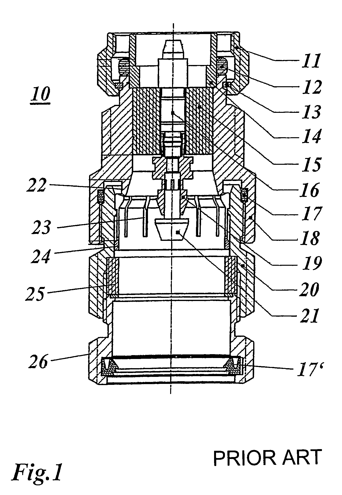
Owing to the various screw connections and seals, the design and fitting of the known cable plug shown in FIG. 1 are complicated and laborious.

Method used


Image

  • Cable plug for a coaxial cable and method for mounting a cable plug of this type
  • Cable plug for a coaxial cable and method for mounting a cable plug of this type
  • Cable plug for a coaxial cable and method for mounting a cable plug of this type

Examples


Embodiment Construction

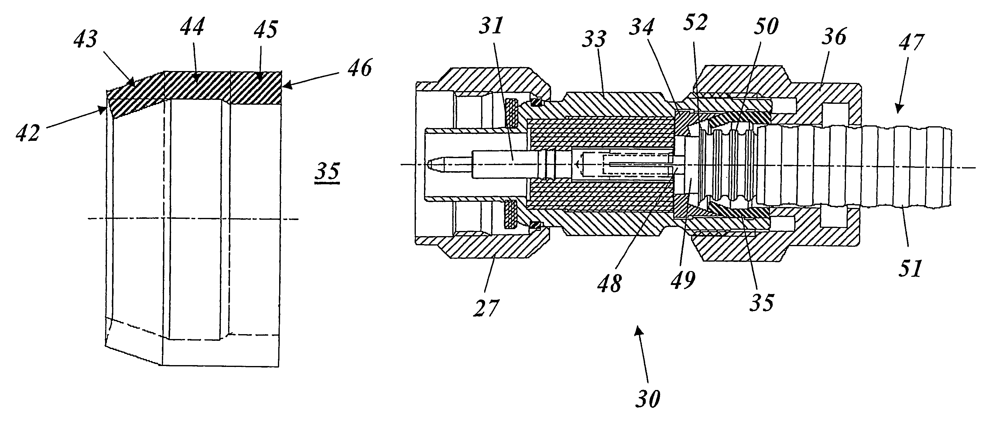
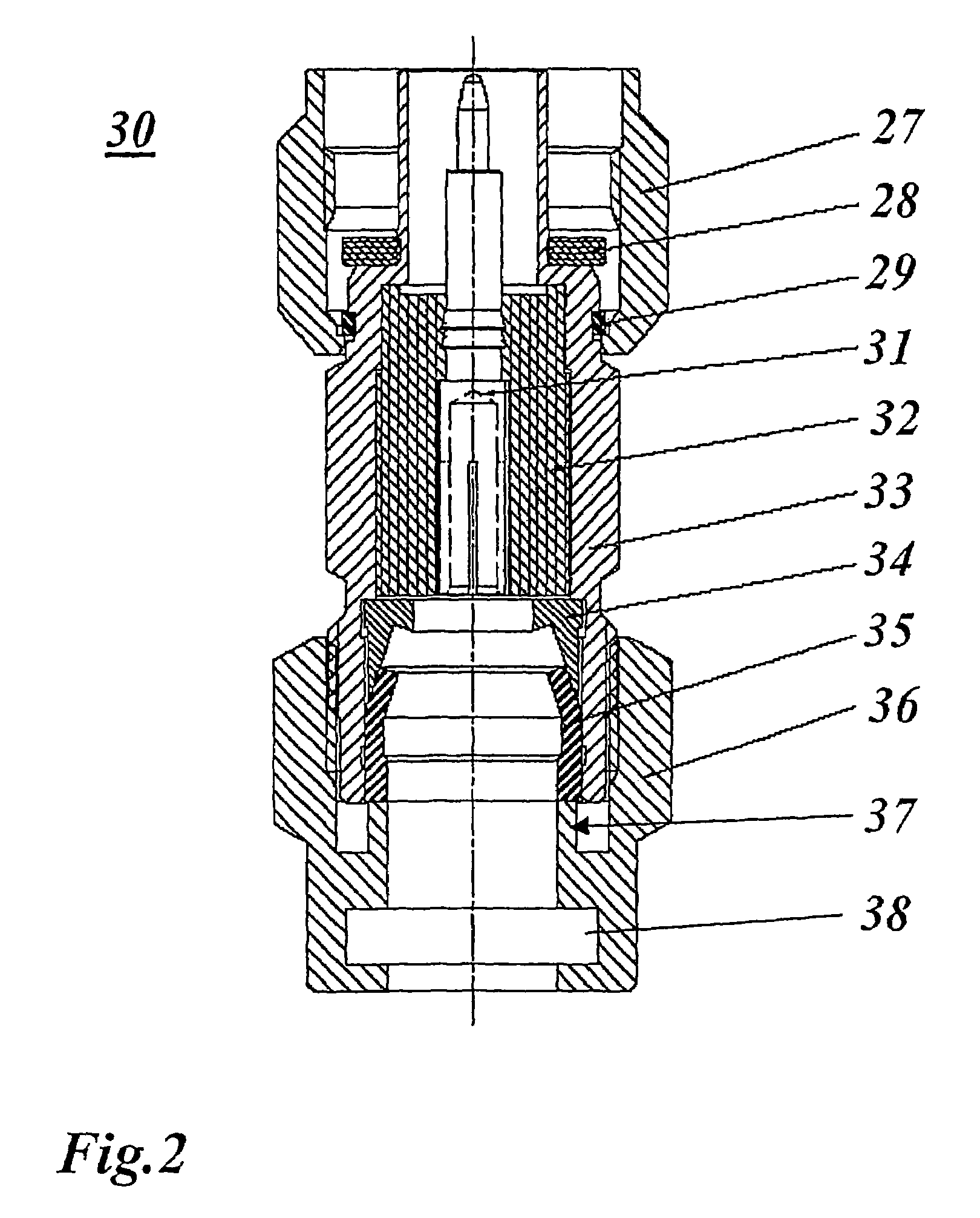
[0037]With reference to FIG. 2, a preferred exemplary embodiment of a cable plug according to the invention is reproduced. The cable plug 30 comprises a housing 33, which concentrically surrounds an inner conductor 31, which is held in insulated fashion e housing by means of an insulator 32. In turn, a union nut 27 is fixed with the aid of a snap ring 29 such that it can be rotated at the plug-in side end of the housing 33. For sealing purposes in interaction with the female connector, a seal 28 is provided. In order to fix, make contact with and seal the outer conductor of the coaxial cable, a screw connection is provided which comprises three elements, namely an adjusting ring 34 consisting of metal, for example brass, which is inserted into the housing 33 and is supported on a shoulder at the level of the insulator 32, a sealing and clamping ring 35 and a nut 36. The nut 36 can be screwed onto the housing 33 at the cable-side end, the cable being guided through a central through-...


PUM

PropertyMeasurementUnit
electrically conductiveaaaaaaaaaa
axial forceaaaaaaaaaa
frictionaaaaaaaaaa

Abstract

A cable plug for a coaxial cable, in particular comprising an external corrugated conductor, comprises an electrically conductive housing, which concentrically surrounds an insulated internal conductor, in addition to fixing elements which are used to connect the external conductor of the coaxial cable electrically and mechanically to the housing of the cable plug. The cable plug permits a particularly simple configuration and assembly. To achieve this, the fixing elements ensure a fixed and sealed connection between the external conductor of the coaxial cable and the housing of the cable plug.

Description

BACKGROUND OF THE INVENTION[0001]1) Field of the Invention[0002]The present invention relates to the field of plug-in connector technology for coaxial cables and to a method for fitting such a cable plug.[0003]2) Description of Related Art[0004]Coaxial cables, as are used nowadays, for example, in the sector of base stations of mobile radio networks, have, in a concentric arrangement, an inner conductor and an outer conductor, which are insulated from one another by a dielectric lying therebetween. The outer conductor is generally surrounded by a protective outer sheath consisting of plastic. The outer conductor of a coaxial cable can be in the form of metallic braiding (at frequencies which are not too high). However, it can also be in the form of a continuous tube. If an increased flexibility of the cable is not required, the tube of the outer conductor may have smooth walls. In order to achieve increased flexibility, corrugated tubes or hoses consisting of metal are generally use...

Claims


Application Information

Patent Timeline
Patent Type & Authority Patents(United States)
IPC IPC(8): H01R9/05
CPCH01R13/5205H01R24/564Y10T29/49169H01R2103/00
Inventor STUDERUS, PETER
Owner HUBERSUHNER AG
Learn More