
Fixing device and image forming apparatus with horizontally moving separating claw

a technology of fixing device and image forming apparatus, which is applied in the direction of electrographic process apparatus, instruments, optics, etc., can solve the problems of recording material enwinding heat roller, performance of separation, and scratches on the heat roller surface which are sufficient to generate the defects of image on recording material, so as to maintain the separation performance and excellent image forming

Inactive Publication Date: 2008-12-09
KONICA MINOLTA BUSINESS TECH INC
View PDF3 Cites 6 Cited by
  • Summary
  • Abstract
  • Description
  • Claims
  • Application Information

AI Technical Summary

Benefits of technology

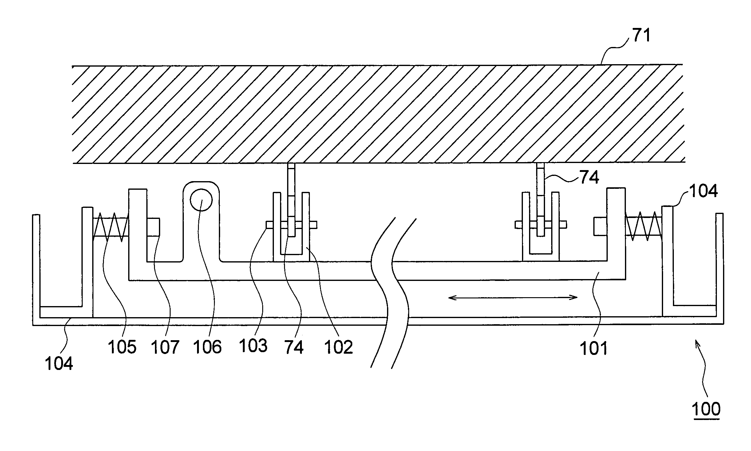
"The present invention relates to a fixing device and image forming apparatus that can improve image quality and reduce defects in the image. This is achieved by making the moving velocity of the separation claw more appropriate, which involves fixing a toner image onto a recording material and then separating it from the fixing member using a separation claw. The image forming apparatus includes the fixing device and a separation claw moving device that moves the separation claw along the surface of the fixing member. By controlling the moving velocity of the separation claw, this technology can maintain the separation performance of the separation claw and achieve excellent image forming."

Problems solved by technology

In the nip area in the fixing device, there has been occurred a problem that the recording material enwinds the heat roller.
These scratches on the heat roller appear on the image of the recording material as defects, which has been a problem for image forming apparatuses which are required to have high quality.
However, though the separation claws move in the direction parallel to the rotation axis of the heat roller, if the moving velocity of the separation claw (a separation claw's moving distance along the surface of heat roller per unit time) is low, the scratches which are sufficient to generate the defects in the image on the recording material will occur on the heat roller surface.
Also, if the moving velocity of separation claw is high, a problem occurs in performance of separation.

Method used


Image

  • Fixing device and image forming apparatus with horizontally moving separating claw
  • Fixing device and image forming apparatus with horizontally moving separating claw
  • Fixing device and image forming apparatus with horizontally moving separating claw

Examples


Embodiment Construction

[0021]An embodiment of an image forming apparatus of the present invention will be described below.

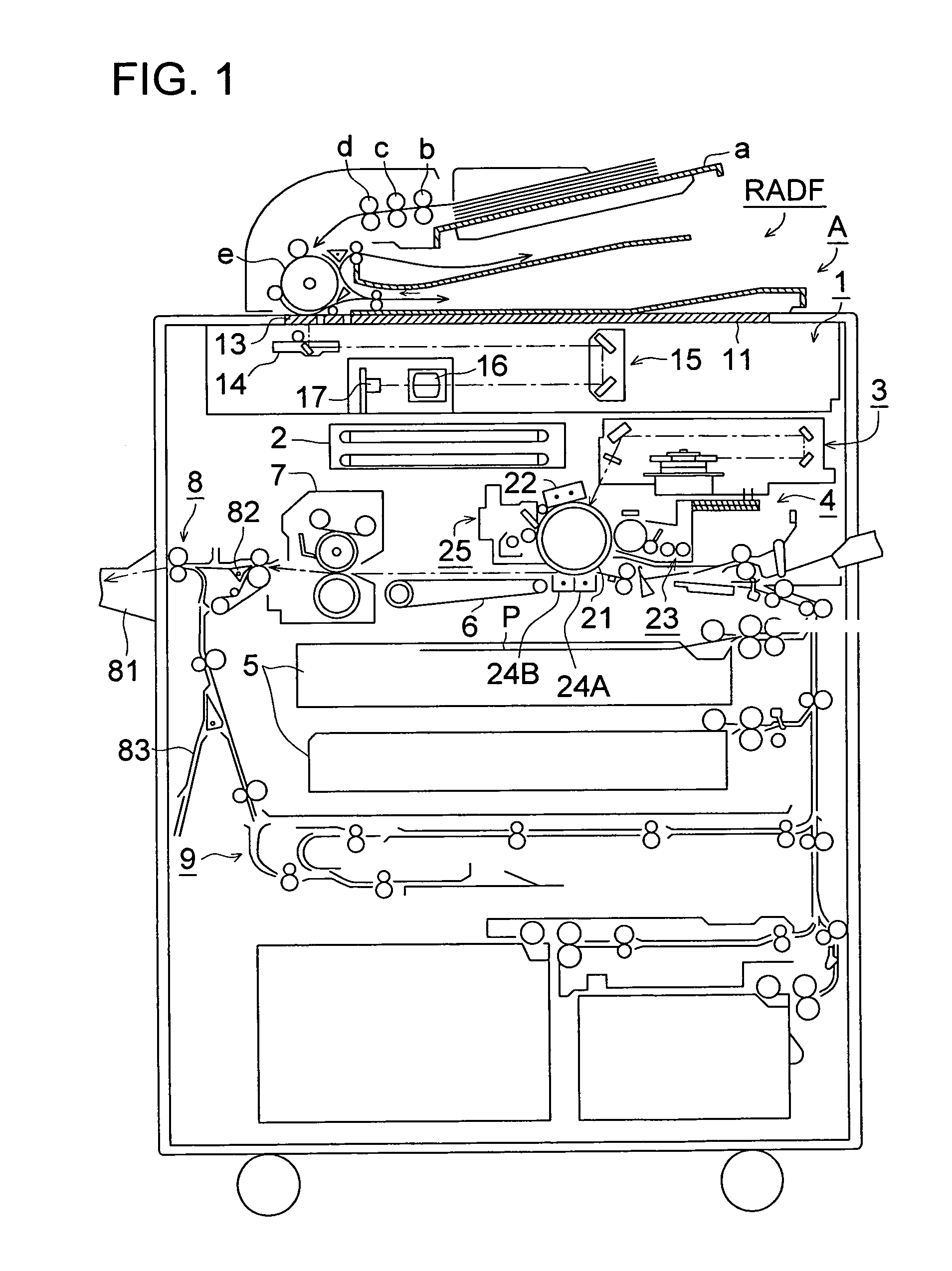
[0022]FIG. 1 is a diagram explaining total configuration of the image forming apparatus. The image forming apparatus shown in FIG. 1 is composed of duplex document automatic feeding device RADF and image forming apparatus main body A.

[0023]Duplex document automatic feeding device RADF is located in an upper part of image forming apparatus main body A and able to be opened and closed. A document on document feeding tray a is conveyed by sheet feeding roller b, separation roller c, registration roller d and conveyance drum e.

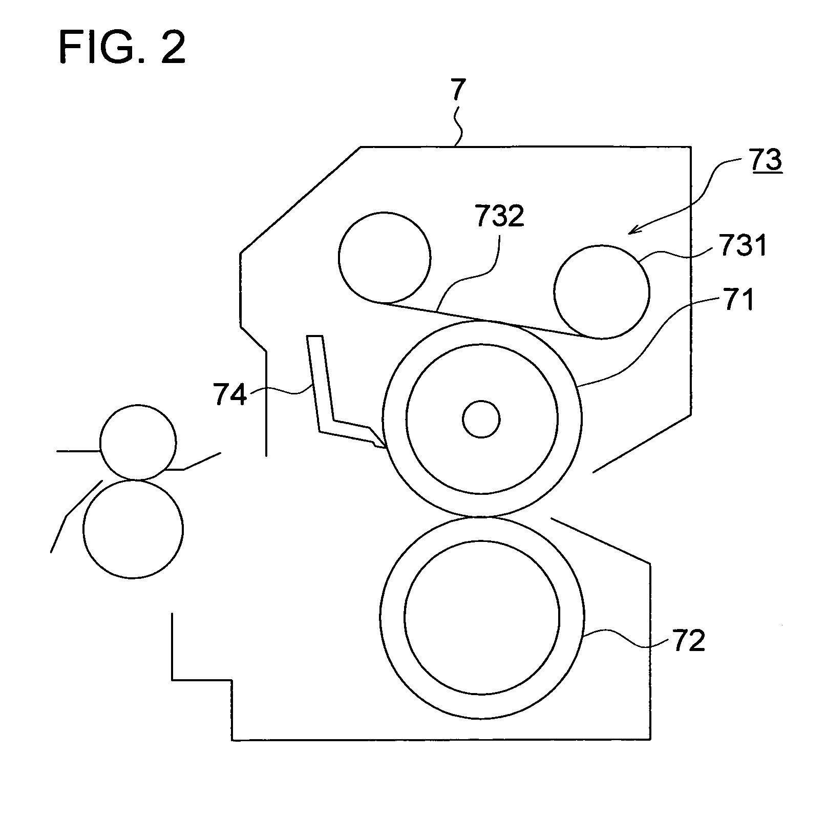
[0024]Image forming apparatus main body A is composed of image reading device 1, control device 2, image writing device 3, image forming device 4, recording material storing device 5, conveyance transmission device 6, fixing device 7, sheet ejecting device 8, and re-conveyance device 9.

[0025]An optical system of image reading device 1 is composed of exposure unit 14 ...


PUM


Abstract

The fixing device and image forming apparatus employ a horizontally moving claw for separating a sheet on which a toner image has been fixed. The claw moves in a horizontally reciprocating manner at a velocity between 0.001 mm / seconds to 0.1 mm / seconds. Moving at that speed, it has been found to reduce scratching of the fixing drum. The device and image forming apparatus also employ a claw having a width between 1.0 mm and 5.0 mm. The claw contacts the drum with a pressure in a range of 3.0×9.8 mN to 7.0×9.8 mN.

Description

[0001]This application claims priority from Japanese Patent Application No. 2005-260424 filed on Sep. 8, 2005, which is incorporated hereinto by reference.BACKGROUND OF THE INVENTION[0002]The present invention relates to a fixing device which fixes a toner image on a recording material and to an image forming apparatus having the fixing device to form an image, such as a coping machine, a printer and a facsimile machine.[0003]The image forming apparatus such as the coping machine, the printer, and the facsimile machine utilizing an electro photographic method forms an image on the recording material by transferring a toner image from a surface of an image carrier such as a photoreceptor and an intermediate transfer member and by fixing the transferred toner image.[0004]In a fixing device commonly used for in the image forming apparatus, a nip area is formed by 2 rollers including a heat roller and a pressure roller, and the recording material is caused to pass through the nip area t...

Claims


Application Information

Patent Timeline
Patent Type & Authority Patents(United States)
IPC IPC(8): G03G15/20
CPCG03G15/2028
Inventor SHIOKAWA, YASUOKOSUGI, AKIRAFUJII, RITSUO
Owner KONICA MINOLTA BUSINESS TECH INC
Learn More