Hollow structural member

a technology of structural members and hollow parts, applied in the direction of engine components, wind energy generation, machines/engines, etc., can solve the problem that the pole makes the transportation task somewhat difficul

Active Publication Date: 2008-12-16
VALMONT INDUSTIES INC
View PDF15 Cites 88 Cited by
  • Summary
  • Abstract
  • Description
  • Claims
  • Application Information

AI Technical Summary

Benefits of technology

[0011]Yet another object of the invention is to provide a wind turbine tower of the type describ

Problems solved by technology

In either case, the pole sections or the assembled pole must be shipped to the job site a

Method used


Image

  • Hollow structural member
  • Hollow structural member
  • Hollow structural member

Examples


Embodiment Construction

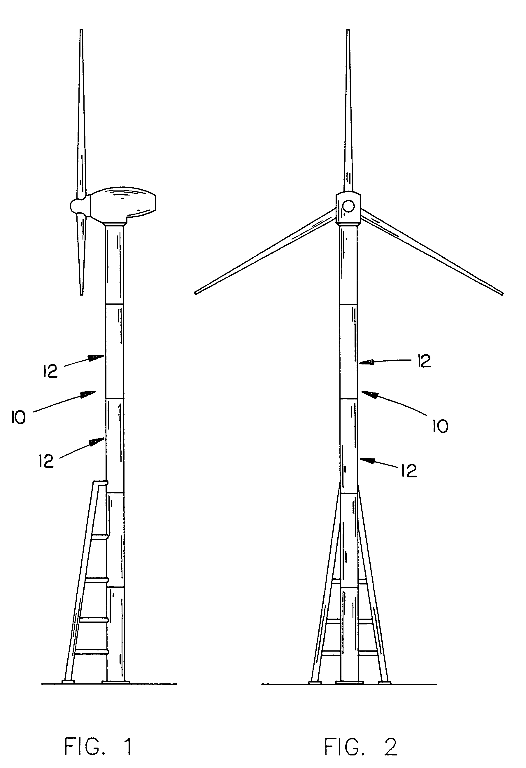
[0022]The numeral 10 refers to a hollow, elongated structural member such as a wind turbine tower as illustrated in assignee's U.S. Pat. Nos. 6,278,198; 6,505,785 and 6,522,025. In the wind turbine towers of U.S. Pat. Nos. 6,278,198; 6,505,785 and 6,522,025, guide rails are provided on the exterior surface of the tower to enable a wind turbine support or sled to move along the length of the tower. The instant invention eliminates the need for rails, as will be described hereinafter.

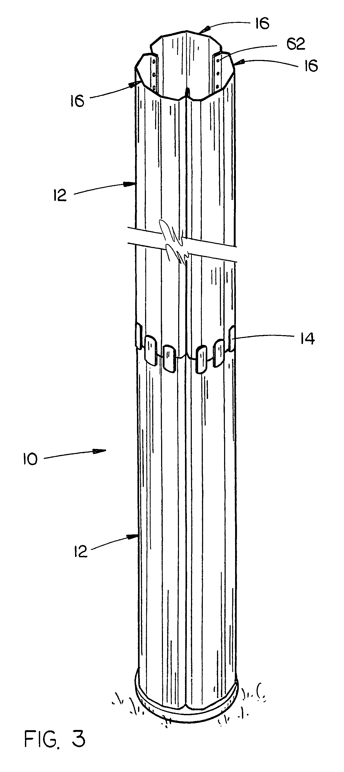
[0023]Tower 10 is constructed with a plurality of elongated hollow metal pole sections 12 which are secured together in an end-to-end relationship by splice plate assemblies 14, such as described in assignee's pending patent application Ser. No. 10 / 463,155, filed Jun. 17, 2003, entitled A TWO-PLATE SPLICE CONNECTION ASSEMBLY. The pole sections 12 may be tapered or non-tapered as desired.

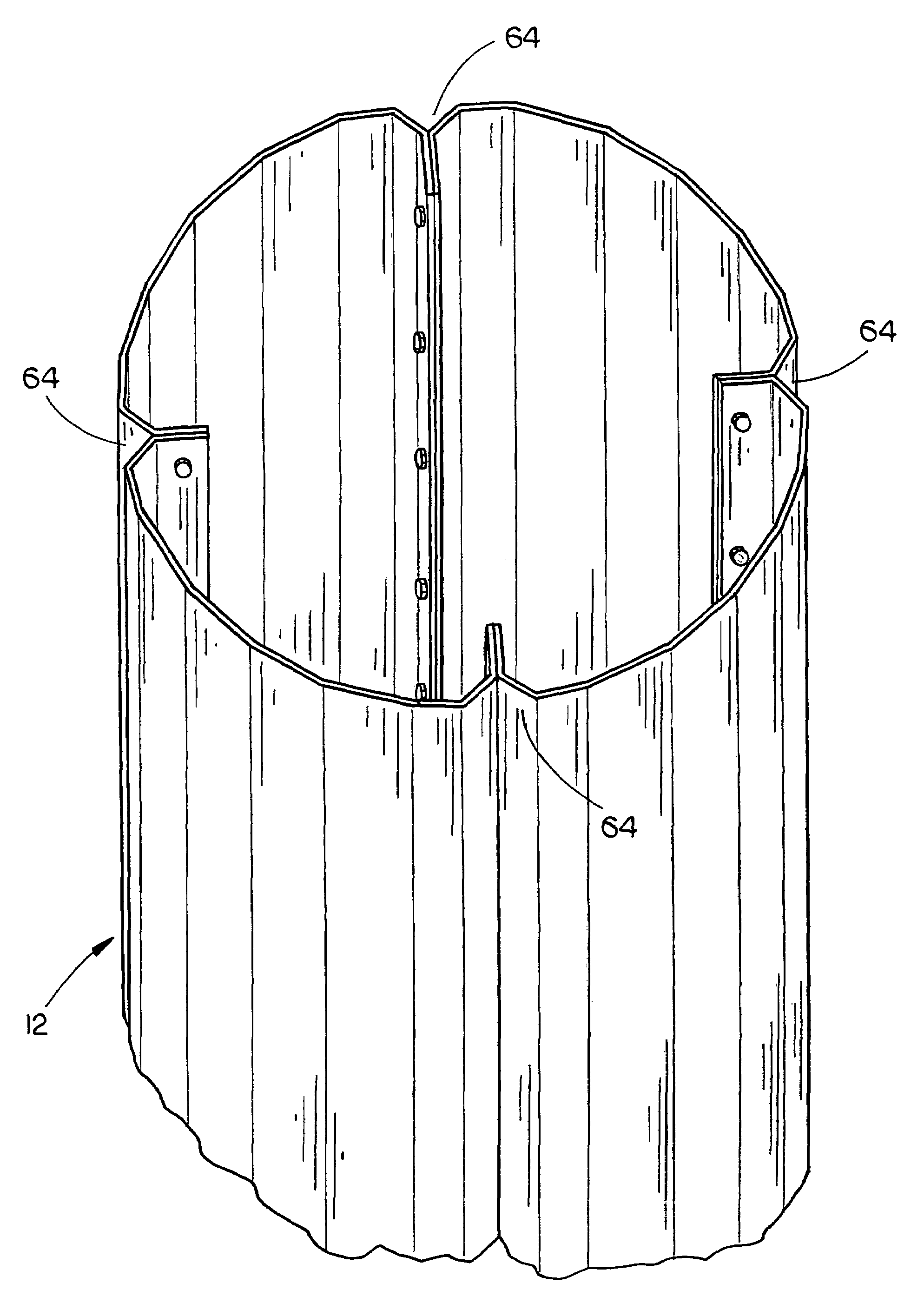
[0024]Each of the pole sections 12 is constructed of a plurality of longitudinally extending peripheral sections 16, pre...


PUM


Abstract

A structural member such as a wind turbine tower comprising a plurality of elongated hollow pole sections secured together in an end-to-end relationship with each of the hollow pole sections comprising a plurality of longitudinally extending peripheral sections joined together. Each of the peripheral sections is bent along at least one longitudinally extending break line to define a plurality of angled wall sections extending between longitudinally inwardly extending edge portions. The edge portions of the peripheral sections are bolted together to form a hollow pole section.

Description

BACKGROUND OF THE INVENTION[0001]1. Field of the Invention[0002]This invention relates to a hollow structural member such as a wind turbine tower or the like.[0003]2. Description of the Related Art[0004]Wind turbines are becoming more popular in the production of electrical energy. The wind turbine normally comprises a rotor-driven generator mounted atop a tower which may reach heights of 70 meters or more.[0005]In assignee's U.S. Pat. Nos. 6,278,198; 6,505,785; and 6,522,025, a wind turbine is shown to be mounted on the upper end of a tubular tower comprised of tubular pole sections secured to one another in an end-to-end fashion. Each of the pole sections in assignee's prior wind turbine towers is comprised of a single sheet of steel material which is bent and welded together to form a cylindrical or tubular pole section. Because the individual pole sections are fabricated at a factory remote from the job site, the pole sections are either welded to one another at the factory or a...

Claims


Application Information

Patent Timeline
IPC IPC(8): E04H12/00
CPCE04H12/08F05B2240/912Y02E10/728
Inventor PERINA, MARK J.
Owner VALMONT INDUSTIES INC
Why Eureka
Try Eureka