Variable flow control method and device between air intake and throttle

a flow control and variable technology, applied in the direction of fuel injection control, combustion engines, machines/engines, etc., can solve the problems of high rotating rate torsion and horsepower, and achieve the effect of effective acceleration more rapidly

Inactive Publication Date: 2008-12-16
CHANG CHUN HSIUNG
View PDF4 Cites 5 Cited by
  • Summary
  • Abstract
  • Description
  • Claims
  • Application Information

AI Technical Summary

Benefits of technology

[0007]The variable flow control method and device between an air intake and a throttle of the present invention is provided with at least one one-way valve with suitable restoring function between the air intake and the throttle (especially for a car), so that mutual corresponding functions can be generated among the one-way valve, an air intake manifold and the throttle of the car to adjust and control an engine, such that the engine can rapidly get various rotating rates corresponding to various degrees of vacuum respectively as in natural or original air taking in a conventional way, and can effectively accelerate more rapidly when the accelerator is trampled rapidly, and reflect the improvements on performances responding to torsion and acceleration of various rotating rates.

Problems solved by technology

In a conventional example of a car, an air intake manifold is provided behind a throttle, all the intake pipe sections before a combustion cylinder generally are in the same length, the degrees of vacuum in the intake pipe sections are higher because of the stronger suction created by the piston of the cylinder during low rotating rates, and the degrees of vacuum in the intake pipe sections are lower during high rotating rates; a longer intake pipe is beneficial to the performance of the torsion in low rotating rates, but is disadvantageous to the performance of torsion and horsepower in high rotating rates.

Method used


Image

  • Variable flow control method and device between air intake and throttle
  • Variable flow control method and device between air intake and throttle
  • Variable flow control method and device between air intake and throttle

Examples


Embodiment Construction

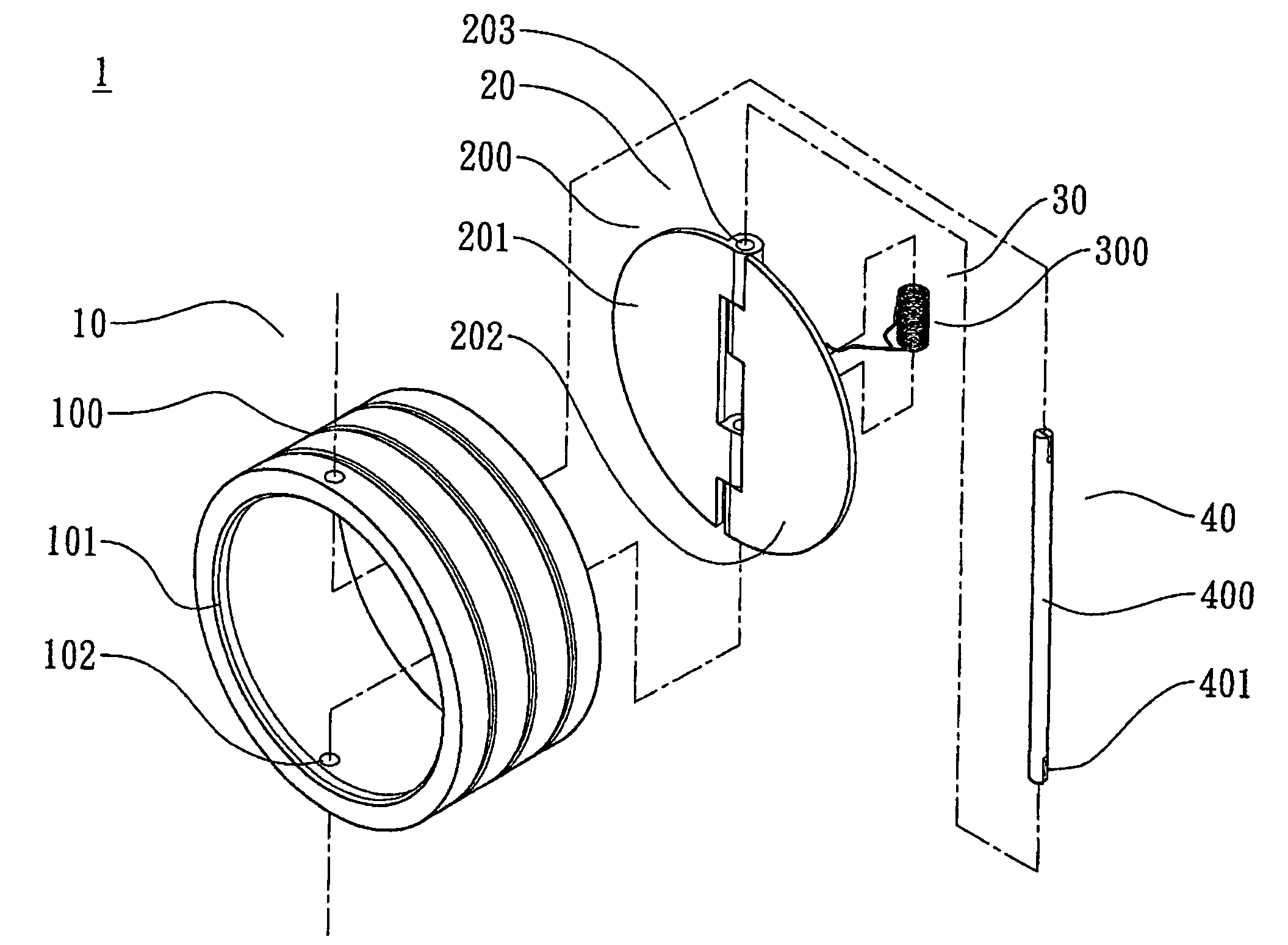
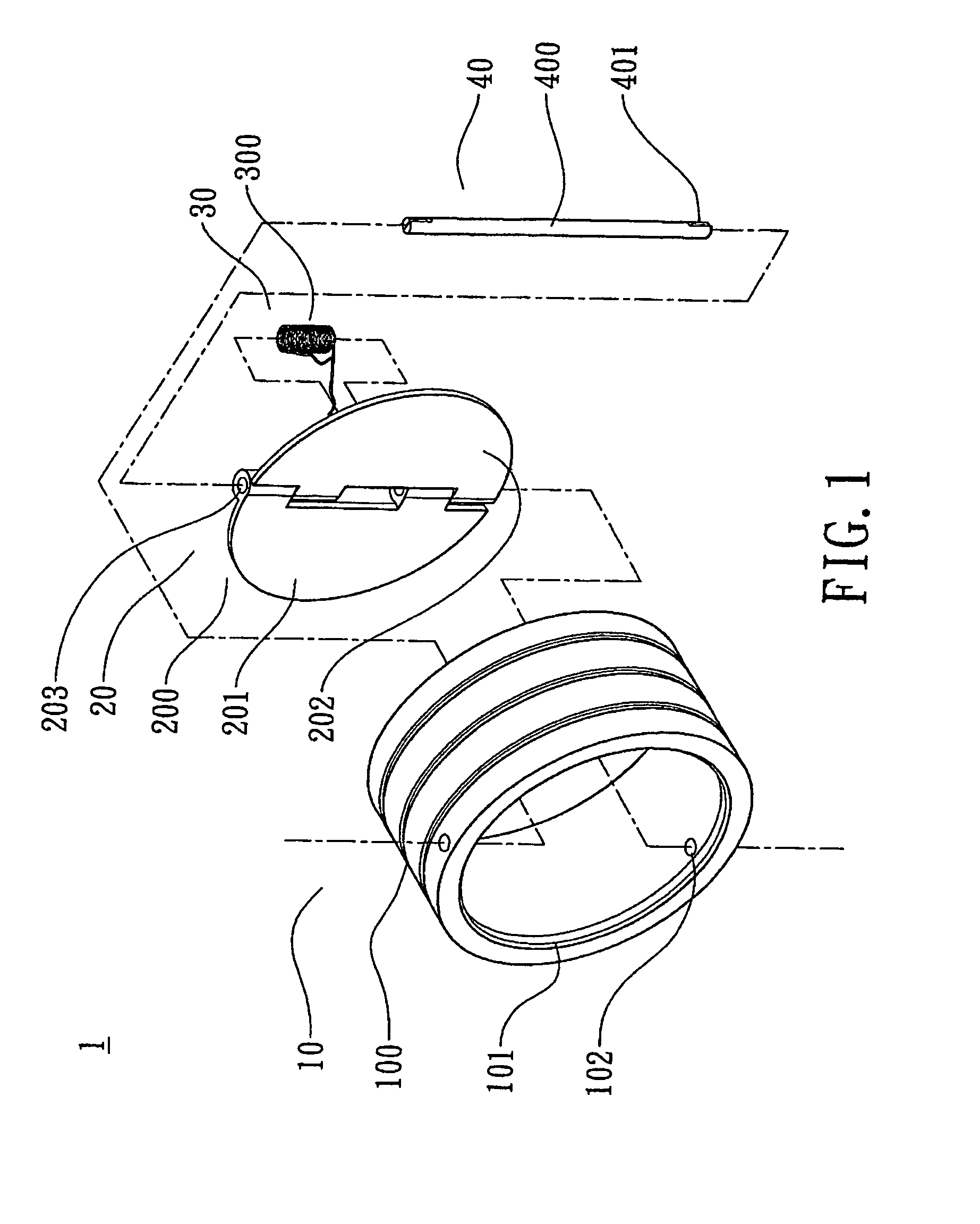
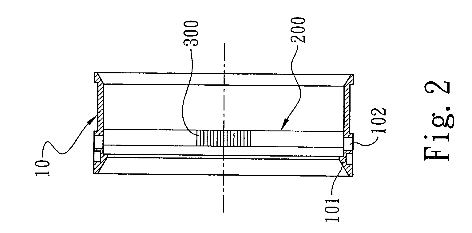
[0012]Referring to FIG. 1-2, a variable flow control device between an air intake and a throttle of an embodiment of the present invention includes at least one one-way valve 1 with suitable restoring function. The one-way valve 1 comprises a fixing portion 10, a one-way operating portion 20 having at least one one-way movable blade 201, a force restoring portion 30 and a supporting portion 40. The fixing portion 10 is consisted of a fixing pipe 100 with a reduced mouth 101 on one end. The hollow space of the fixing pipe 100 is an air-intaking passage. At least one fixing hole 102 is disposed at the fixing pipe body. The one-way operating portion 20 comprises a one-way movable blade set 200 consisted of a pair of movable blades 201, 202 pivoted and coupled with each other. At least one axis hole 203 is provided at the pivoted portion of the movable blades. The force restoring portion 30 comprises at least one spring 300 with restoring force. The supporting portion 40 comprises a fix...


PUM


Abstract

A variable flow control method and device between an air intake and a throttle comprise at least one one-way valve with suitable restoring function between the air intake and the throttle, especially for a fuel-injected car. Corresponding functions can be generated among the one-way valve, an air intake manifold and the throttle to adjust and control an engine so that the engine can rapidly get various rotating rates corresponding to various degrees of vacuum respectively as natural or original air taking can be effectively and rapidly accelerated when the accelerator is trampled rapidly, and reflect the improvement on performances responding to torsion and acceleration of the various rotating rates.

Description

BACKGROUND OF THE INVENTION[0001]1. Field of the Invention[0002]The present invention relates to a variable flow control method and device between an air intake and a throttle, wherein at least one one-way valve with suitable restoring function is provided between the air intake and the throttle to adjust and control an engine, so that the engine can rapidly get various rotating rates corresponding to various degrees of vacuum respectively as in natural air taking, and can control the amount of air needed for combustion in the various rotating rates. The present invention is suitable for applying to engines of vehicles and others for like purposes.[0003]2. Description of the Prior Art[0004]In a conventional intake system of a car, the following concept: “air flow in all the intake pipe sections and passages is asked to keep fluent, in order to reduce or remove any device or mechanism that is probable to hinder air intake” has been the most basic standard.[0005]And in a conventional ...

Claims


Application Information

Patent Timeline
Patent Type & Authority Patents(United States)
IPC IPC(8): F02D7/00
CPCF02D9/02F02D9/102F02D9/10F02B27/02
Inventor CHANG, CHUN-HSIUNG
Owner CHANG CHUN HSIUNG
Why Eureka
Try Eureka