Modular plug and plug installation structure

a technology of installation structure and plugs, which is applied in the direction of coupling devices, two-part coupling devices, electrical devices, etc., can solve the problem of not being able to achieve miniaturization of connectors

Inactive Publication Date: 2008-12-16
FUJITSU LTD
View PDF10 Cites 163 Cited by
  • Summary
  • Abstract
  • Description
  • Claims
  • Application Information

AI Technical Summary

Benefits of technology

[0019]More specifically, the embodiments of the present invention may provide a modular plug and a plug installation structure whereby operability when the modular plug is removed from a connector is improved and the size and the thickness of the connector can be made small.
[0024]According to an embodiment of the present invention, the lock turning-off member is operated to be slid so that the inclination surface operates on the operations lever and engagement of the engaging claw and the connector is turned off. Therefore, in the embodiment of the present invention, unlike the related art, it is not necessary to turn off the lock of the modular plug by clamping the operations lever obliquely extended from the plug main body with fingers. Hence, even if the connectors are closely provided so that installation gaps of the modular plugs are narrowed, it is possible to securely attach or detach the modular plugs to or from the connectors. Accordingly, while the operability is kept, it is possible to realize high density installation of the modular plugs to the connectors.
[0025]In addition, when the modular plug is removed from the connector, it is necessary to slide the lock turning-off member in an insertion direction so that the modular plug is pulled out from the connector. Accordingly, it is not possible to pull out the modular plug from the connector in error. Hence, safety of the modular plug at the time of installation can be improved.

Problems solved by technology

Here, FIG. 5 is a view showing a disadvantage of the first related art plug.
Hence, it is not possible to achieve miniaturization of the connectors.

Method used


Image

  • Modular plug and plug installation structure
  • Modular plug and plug installation structure
  • Modular plug and plug installation structure

Examples


Embodiment Construction

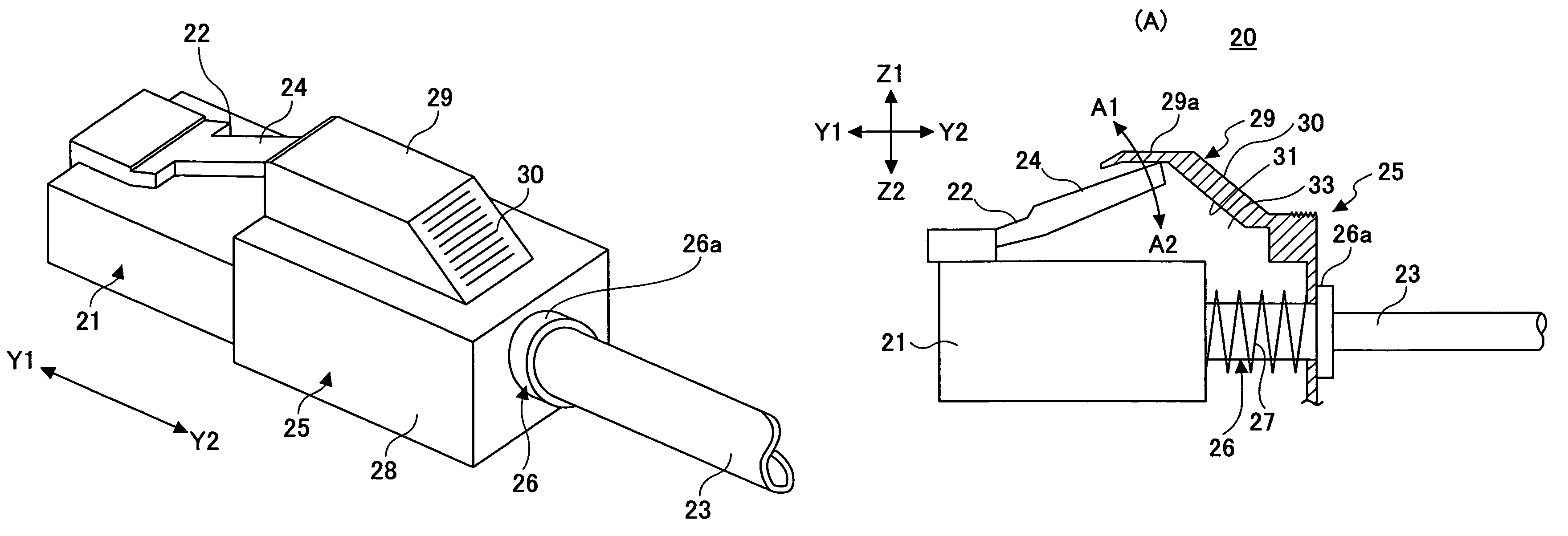
[0040]A description is given below, with reference to the FIG. 6 through FIG. 13 of embodiments of the present invention.

[0041]FIG. 6 is a perspective view of a plug 20 of an embodiment of the present invention. FIG. 7 is plan view and front view of the plug 20 of the embodiment of the present invention. FIG. 8 is a view showing operations of the plug 20 of the embodiment of the present invention.

[0042]Parts of the connector where the plug 20 is attached or detached have the same configuration as those shown in FIG. 1 through FIG. 5 are given the same reference numbers for explanation.

[0043]The plug 20 includes a plug main body 21, a lock claw 22, a lever part 24, a lock turning-off member 25, and others. This plug 20 corresponds to the standard of RJ-45.

[0044]The plug body 21 is resin molded. A contact (not shown) electrically connected to the connector 1 is provided inside the plug body 21. In addition, a cable 23 is connected to the plug main body 21 and electrically connected to...


PUM


Abstract

An modular plug includes a plug main body that can be inserted into and removed from a connector; an engaging claw configured to engage the plug main body with the connector; and an operations lever configured to turn off engagement of the plug main body and the connector by the engaging claw; wherein a lock turning-off member is provided at the plug main body so that the lock turning-off member can be slid in inserting and removing directions; an inclination surface of the lock turning-off member is formed in a position facing the operations lever; and the inclination surface operates the operation lever accompanying sliding in the inserting direction of the lock-turning off member so that the engagement of the engaging claw and the connector is turned off.

Description

BACKGROUND OF THE INVENTION[0001]1. Field of the Invention[0002]The present invention generally relates to modular plugs and plug installation structures, and more specifically, to a modular plug having an operations lever for turning off a lock with a connecter when the modular plug is pulled out from the connector and a plug installation structure.[0003]2. Description of the Related Art[0004]Generally, when an electronic device is connected to another electronic device by a cable or the like, a connector and a plug are used. In this case, a cable plug is provided at a cable side and a connector where this cable plug is installed is provided at an electronic device side. Recently and continuously, it has been desired that size and thickness of the electronic device in which the connector is provided be made small and operability of the electronic device be improved. Therefore, cable plugs which correspond to such miniaturization and by which operability is attempted to be improved ...

Claims


Application Information

Patent Timeline
Patent Type & Authority Patents(United States)
IPC IPC(8): H01R13/627
CPCH01R13/6272H01R13/6335H01R24/64
Inventor KUSUDA, KIYONORIABE, HIROYUKIKADOYA, HIROSHISATO, HISATO
Owner FUJITSU LTD
Why Eureka
Try Eureka