
Method for developing latent fingerprints

a technology of latent fingerprints and apparatuses, applied in the field of apparatuses for developing latent fingerprints, can solve the problems of unwanted spillage, increased waste, and wrong amount of cyanoacrylate monomer applied to the pad,

Inactive Publication Date: 2008-12-16
WEAVER DAVID E +1
View PDF14 Cites 2 Cited by
  • Summary
  • Abstract
  • Description
  • Claims
  • Application Information

AI Technical Summary

Benefits of technology

The apparatus simplifies the development of latent fingerprints by eliminating guesswork in chemical application, reducing waste, and enabling safe, efficient use in field operations with minimal equipment, adaptable to various object sizes and environments.

Problems solved by technology

There are several disadvantages with the kits of the '579 and '515 patents.
The user must physically add the cyanoacrylate monomer to a pad or plug which may result in unwanted spillage or a wrong amount of cyanoacrylate monomer applied to the pad.
The kits also consist of multiple components which increases the complexity of using the kits as well as increases the amount of waste.
The principal disadvantages with the '645 patent is that it requires a heat resistent housing and the use of a butane torch, both requirements making the cartridge clumsy and potentially dangerous to use.
The disadvantage with these devices is that they require the use of a propane torch which increases the potential danger of using the devices.
The devices also have multiple components including the need for additional cyanoacrylate to refill the housing, which increases the maintenance of the devices.
As seen in previous devices, this apparatus is very cumbersome to carry and use in field operation, and requires the use of a separate heater and fan which increases the maintenance effort.
The disadvantage with the '946 device is that it is cumbersome to carry and use in the field.
Also, the internal size of the chamber limits the number, size, and shape of the objects that can be placed in the container for testing.

Method used


Image

  • Method for developing latent fingerprints
  • Method for developing latent fingerprints
  • Method for developing latent fingerprints

Examples


Embodiment Construction

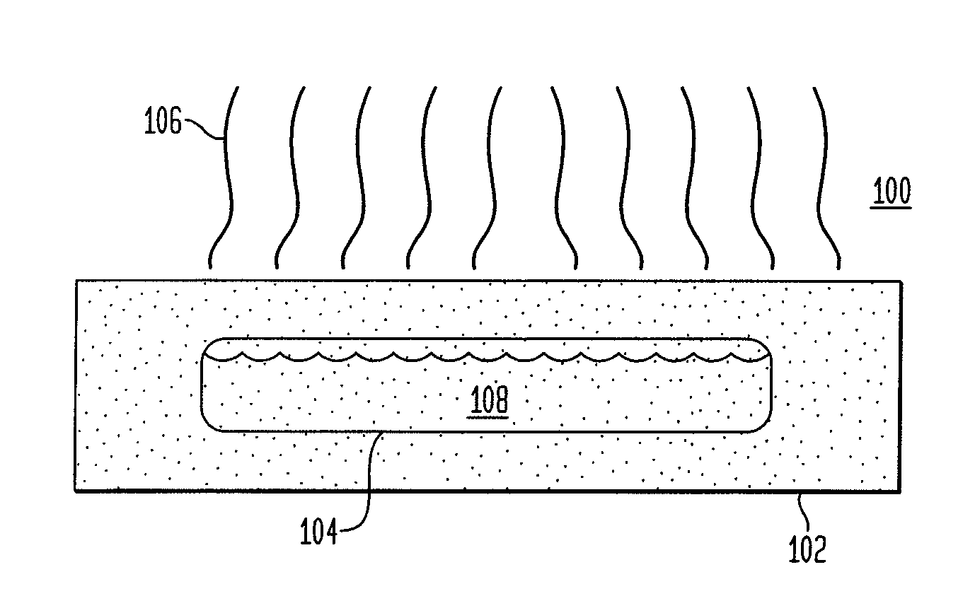
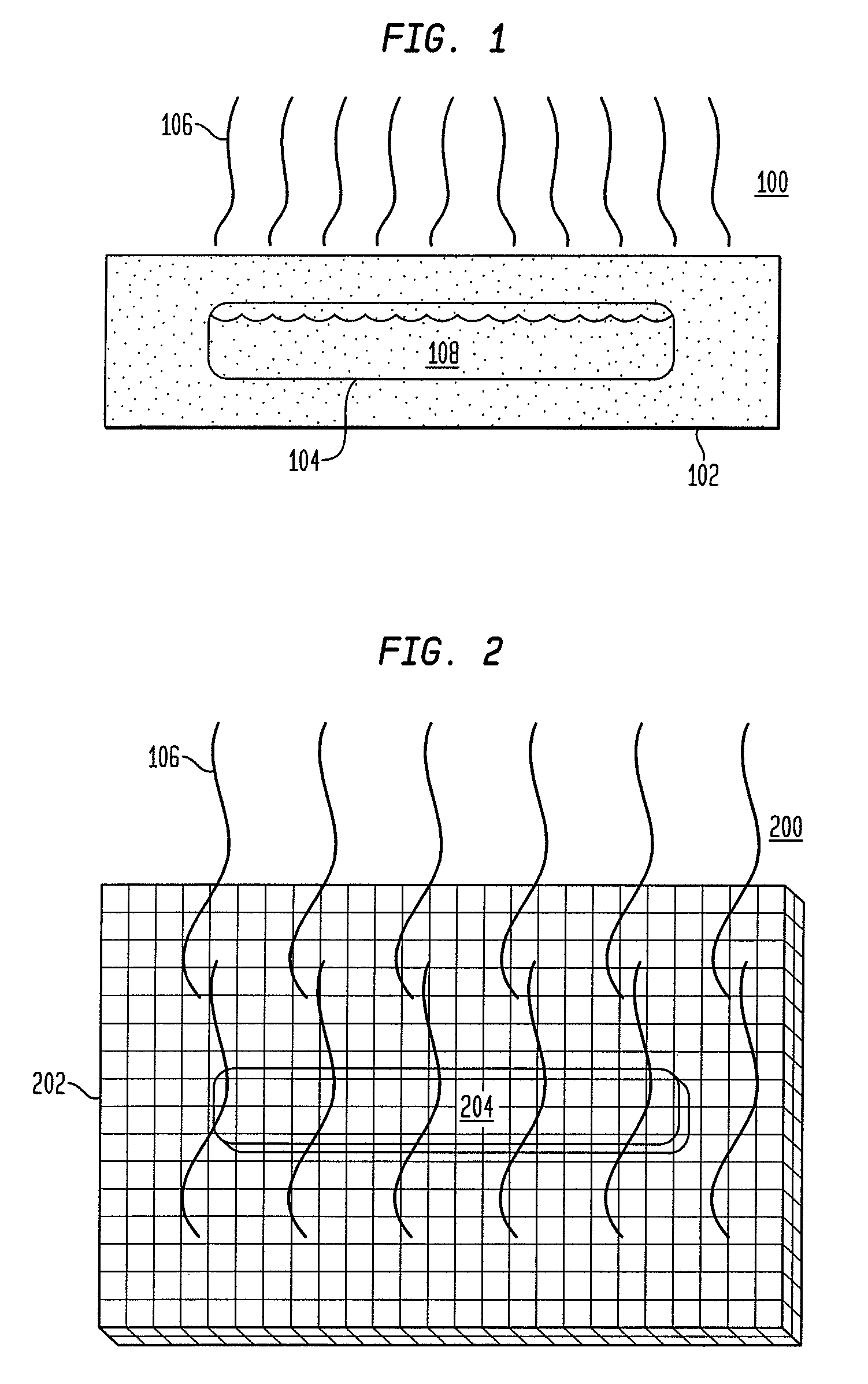
[0027]As shown in FIG. 1, the present invention is an apparatus 100 having a porous, e.g., a cellulosic fiber housing 102 impregnated with any cyanoacrylate catalyst. A breakable capsule 104 (or capsule 104) of liquid cyanoacrylate monomer 108 is contained within an internal chamber of the housing 102.

[0028]In the preferred and simplest embodiment, the housing 102 is a porous material. For example, the housing 102 is a cellulosic fiber material of paper, fibrous textile, plastic, metal, resin, composite, and the like. Alternatively, the housing 102 may be made of a perforated material, e.g., plastic, composite, paper, or resin coated paper, that has holes, perforation, slits, or mesh. Regardless of the particular material, the housing 102 must have a means for emitting vapors 106 as well as for containing a cyanoacrylate catalyst. The material of the housing 102 is preferably impregnated with cyanoacrylate catalyst. It is well known to one of ordinary skill in the relevant art to im...


PUM

PropertyMeasurementUnit
diameteraaaaaaaaaa
lengthaaaaaaaaaa
areaaaaaaaaaaa

Abstract

A method for developing latent fingerprints includes placing an apparatus in an area having one or more objects. The apparatus has a breakable capsule containing a cyanoacrylate monomer disposed within an internal chamber of a housing containing a cyanoacrylate catalyst and being adapted for emitting vapors. The housing is impregnated with the cyanoacrylate catalyst or has a layer of cyanoacrylate catalyst on a portion of its interior surface. The apparatus optionally has a breakable capsule breaking mechanism for assisting a user in breaking the breakable capsule within the housing. The user breaks the breakable capsule, causing the cyanoacrylate monomer spilling from the breakable capsule to react with the cyanoacrylate catalyst contained in the housing to create vapor fumes. The vapor fumes contact an object being tested to reveal any latent fingerprints on the object.

Description

CROSS-REFERENCE TO RELATED APPLICATIONS[0001]This application is a divisional application of U.S. application Ser. No. 11 / 406,096, filed Apr. 18, 2006, now U.S. Pat. No. 7,182,817 which claims the benefit of U.S. Application No. 60 / 672,285, filed Apr. 18, 2005.BACKGROUND[0002]1. Technical Field[0003]The present invention relates to apparatuses for developing latent fingerprints and the method of use thereof, and in particular, to a portable and disposable apparatus containing a cyanoacrylate catalyst and a cyanoacrylate monomer which upon combination thereof creates a cyanoacrylate vapor used in the quick and efficient development of latent fingerprints.[0004]2. Related Art[0005]The use of cyanoacrylate monomers and catalysts in the development of latent fingerprints on objects is well known and has been used as such for many years. Specifically, it is the reaction of the cyanoacrylate monomer and catalyst that creates a microcrystalline vapor which adheres to fingerprints. Once the...

Claims


Application Information

Patent Timeline
Patent Type & Authority Patents(United States)
IPC IPC(8): A61B5/117
CPCA61B5/1172G06K2009/00946G06V40/155
Inventor WEAVER, DAVID E.WEAVER, ORDIS G.
Owner WEAVER DAVID E
Learn More