Solid oxide fuel cell stack

a fuel cell and solid oxide technology, applied in the field of modules for solid oxide fuel cell stacks, can solve the problem of requiring additional spacer members

Inactive Publication Date: 2008-12-16
LG FUEL CELL SYST
View PDF7 Cites 145 Cited by
  • Summary
  • Abstract
  • Description
  • Claims
  • Application Information

AI Technical Summary

Benefits of technology

[0005]Accordingly the present invention seeks to provide a novel module for a f...

Problems solved by technology

A problem with this arrangement is that additional spacer member...

Method used


Image

  • Solid oxide fuel cell stack
  • Solid oxide fuel cell stack
  • Solid oxide fuel cell stack

Examples


Embodiment Construction

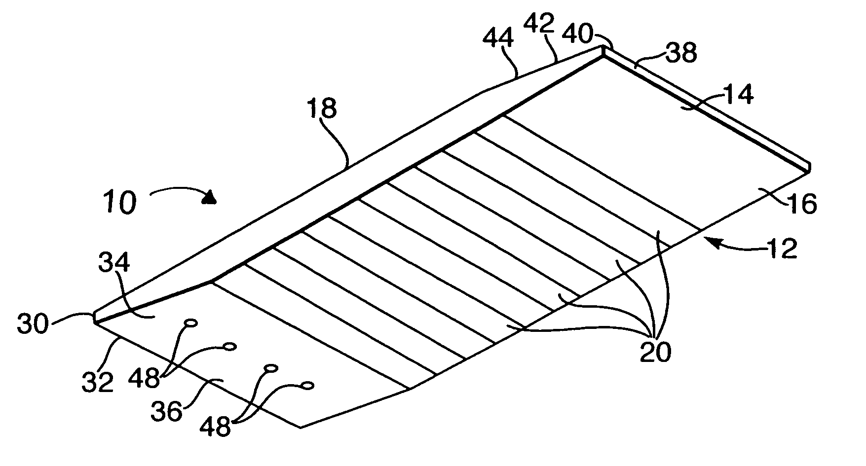
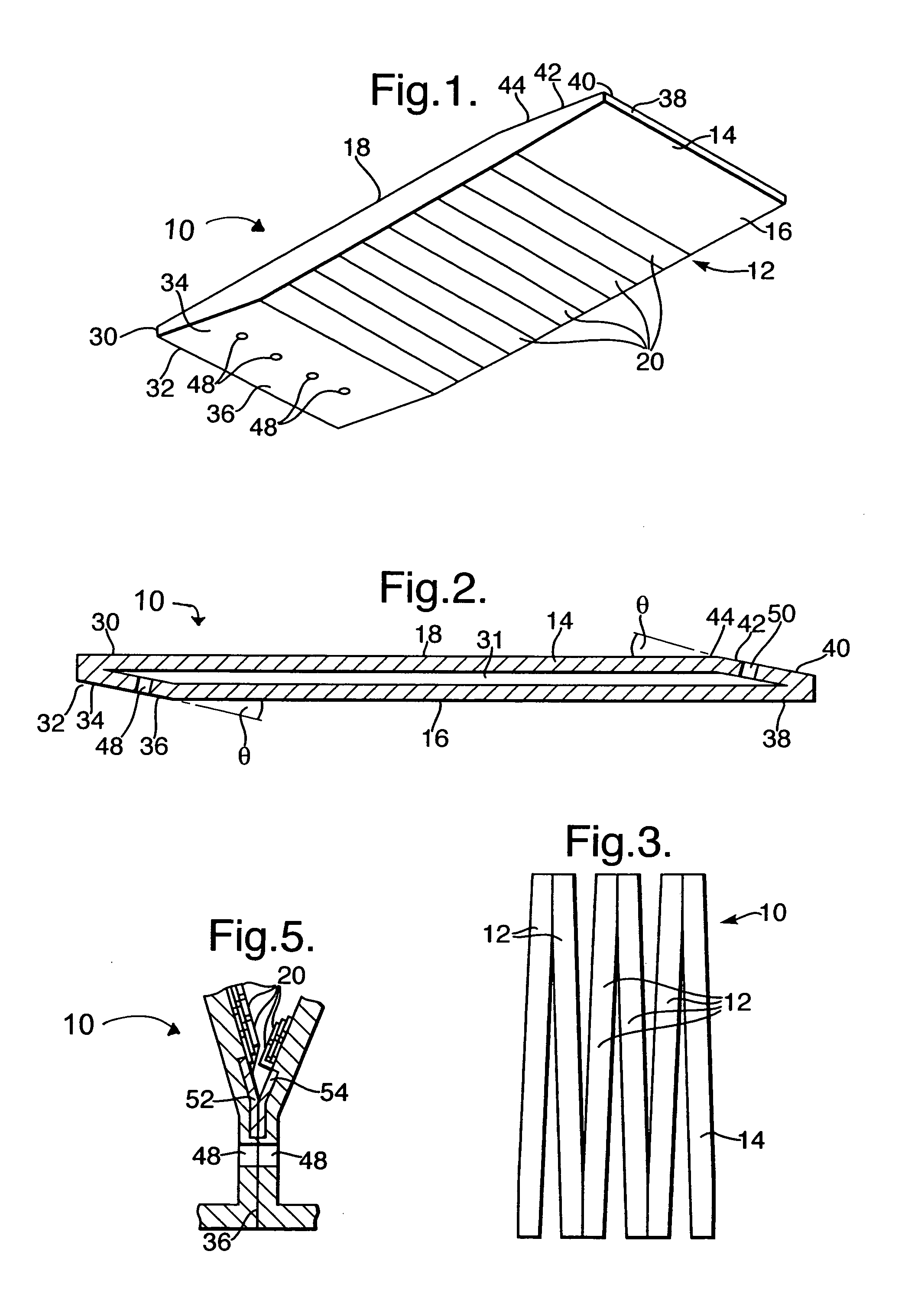
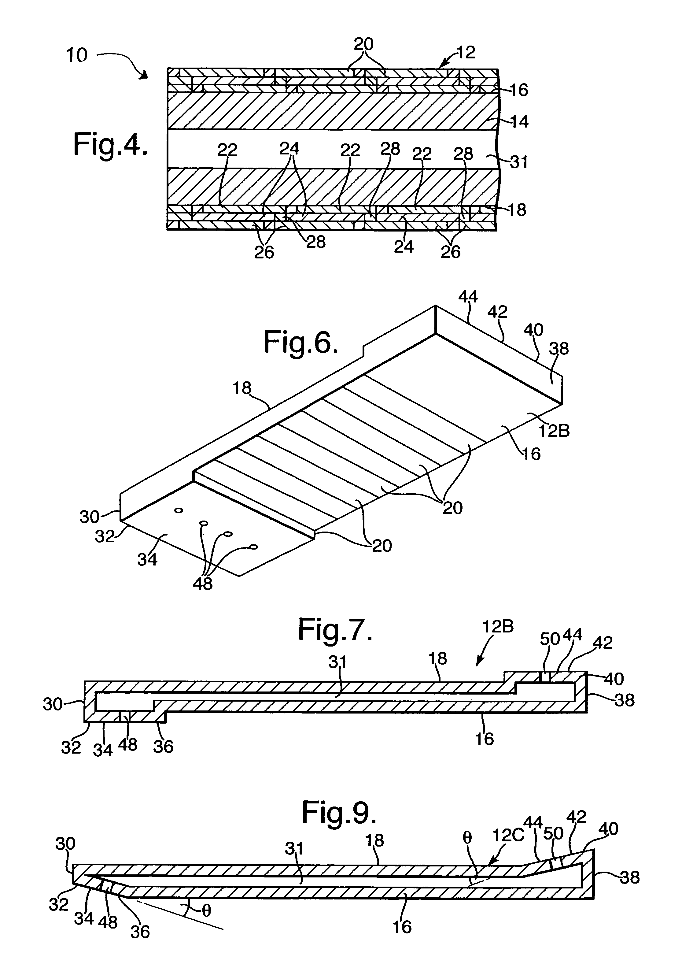
[0051]A solid oxide fuel cell stack 10 according to the present invention is shown in FIGS. 1 to 5. The solid oxide fuel cell stack 10 comprises a plurality of modules 12 arranged within a casing (not shown). Each module 12 comprises an elongate hollow member 14. The hollow members 14 are manufactured from fully or partially stabilised zirconia, alumina, silicon carbide, magnesia doped magnesia aluminate or other suitable ceramic material. Each hollow member 14 has two flat parallel surfaces 16 and 18 upon which, are arranged solid oxide fuel cells 20. The hollow members 14 are porous, or have apertures, to allow fuel to flow to the solid oxide fuel cells 20.

[0052]The solid oxide fuel cells 20 are spaced apart longitudinally along the surfaces 16 and 18 and the solid oxide fuel cells 20 on each of the surfaces 16 and 18 are electrically connected in series.

[0053]Each solid oxide fuel cell 20 comprises an anode electrode 22, a solid oxide electrolyte 24 and a cathode electrode 26. Th...


PUM


Abstract

A fuel cell stack comprises a plurality of modules and each module comprises an elongate hollow member and one passage extending through the hollow member for the flow of a reactant. Each hollow member has a first flat surface and a second flat surface. At least one of the modules includes a plurality of fuel cells arranged on at least one of the first and second flat surfaces. Each module has a first and second integral feature to provide a spacer and a connection with its adjacent modules. The first integral feature comprises a third flat surface and the second integral feature comprises a fourth flat surface. The third flat surface is arranged at an intersecting angle to the first flat surface and the fourth flat surface is arranged at an intersecting angle to the second flat surface.

Description

FIELD OF THE INVENTION[0001]The present invention relates to a module for a fuel cell stack and in particular to a module for a solid oxide fuel cell stack.BACKGROUND OF THE INVENTION[0002]It is known from published International patent application WO03010847A2 to provide a plurality of modules for a fuel cell stack in which each module comprises a hollow member. Each hollow member has at least one passage extending longitudinally through the hollow member for the flow of a reactant. Each hollow member has two parallel flat surfaces and at least one of the modules has a plurality of fuel cells arranged on the flat surfaces of the modules. The end of one module is connected to an end of an adjacent module to allow reactant to flow sequentially through the modules.[0003]In WO03010847A2 spacer members are provided at the ends of the adjacent modules to provide a connection for the flow of reactant from one module to the next, without leaks, and to space apart the flat surfaces of the m...

Claims


Application Information

Patent Timeline
IPC IPC(8): H01M8/10H01M2/00H01M4/86H01M8/02H01M8/04H01M8/12H01M8/24
CPCH01M4/8626H01M8/0247H01M8/0297H01M8/1286H01M8/2425H01M8/249H01M8/04201H01M8/0637H01M2008/1293Y02E60/521Y02E60/525Y02E60/50H01M8/0263
Inventor WRIGHT, GARYHART, NIGEL TAGNEW, GERARD DBURROWS, CHRISTOPHER
Owner LG FUEL CELL SYST
Why Eureka
Try Eureka