Information processing method and apparatus for finding position and orientation of targeted object
a technology for information processing and object position, applied in the direction of instruments, diagnostic recording/measuring, diagnostics, etc., can solve the problems of insufficient accuracy and stability of obtained solutions, inability to find solutions, and difficulty in identifying indices
- Summary
- Abstract
- Description
- Claims
- Application Information
AI Technical Summary
Benefits of technology
Problems solved by technology
Method used
Image
Examples
first embodiment
[0030]A position-and-orientation measuring apparatus according to a first embodiment of the present invention measures the position and orientation of an arbitrary targeted object to be measured. The position-and-orientation measuring apparatus according to the embodiment and a position-and-orientation measuring method therefor are described below.
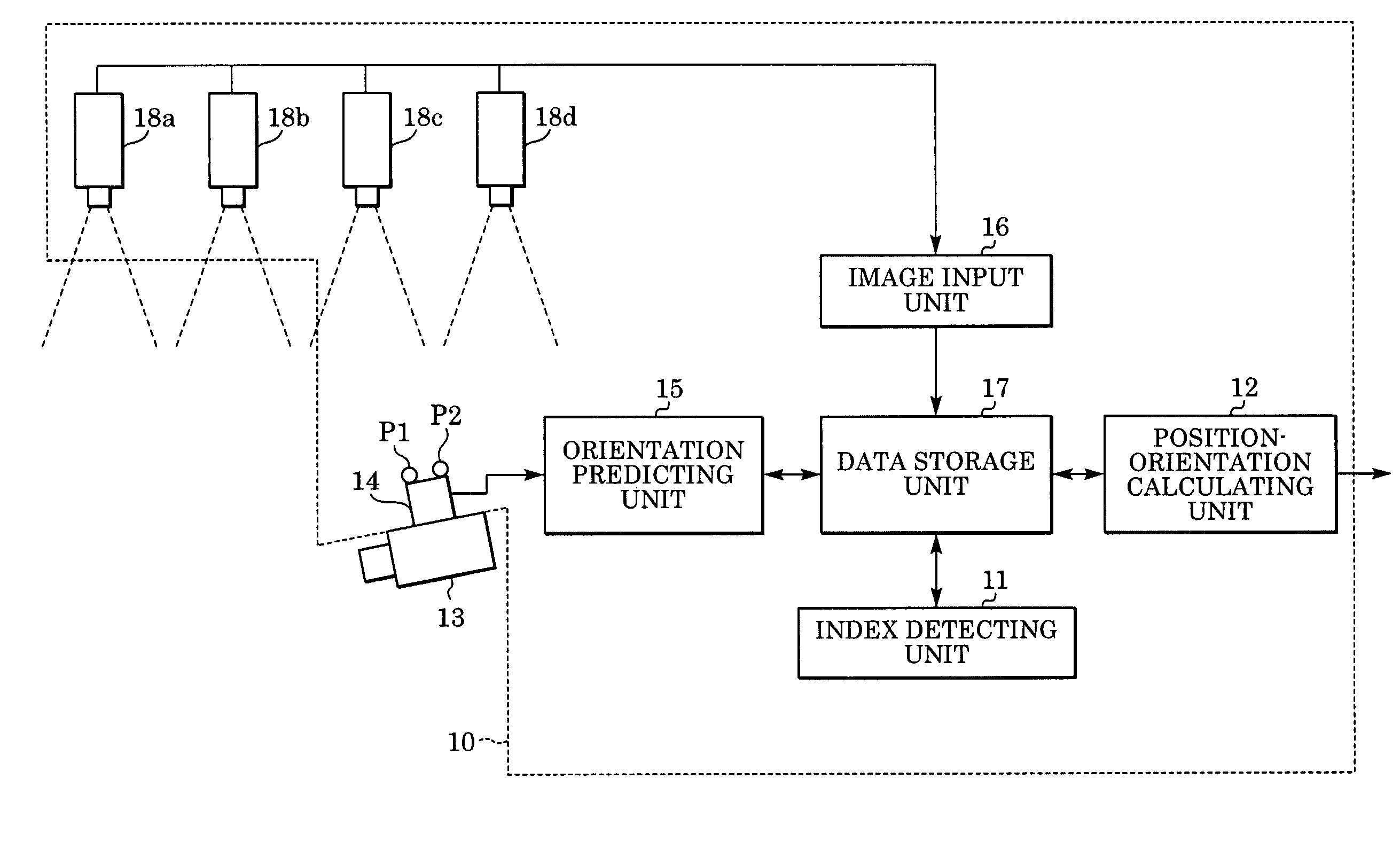
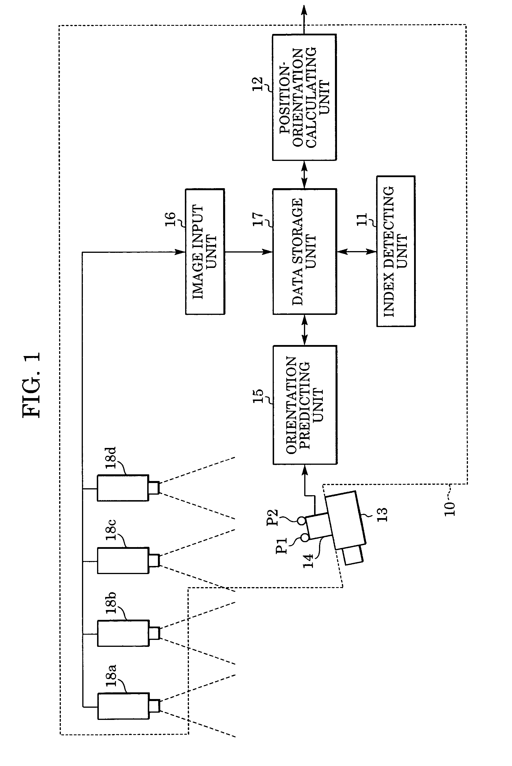
[0031]FIG. 1 shows the configuration of a position-and-orientation measuring apparatus 10 according to the first embodiment. As shown in FIG. 1, the position-and-orientation measuring apparatus 10 includes bird's-eye view cameras 18a, 18b, 18c, and 18d, an image input unit 16, a data storage unit 17, an index detecting unit 11, an orientation sensor 14, an orientation predicting unit 15, and a position-orientation calculating unit 12. The position-and-orientation measuring apparatus 10 is connected to a targeted object 13 to be measured.
[0032]At a plurality of positions on the orientation sensor 14 and / or the targeted object 13, indices Pk...
second embodiment
[0109]A position-and-orientation measuring apparatus according to a second embodiment of the present invention measures the position and orientation of an imaging device. The position-and-orientation measuring apparatus according to the second embodiment and a position-and-orientation measuring method therefor are described below.
[0110]FIG. 6 shows the configuration of the position-and-orientation measuring apparatus according to the second embodiment. As shown in FIG. 6, the position-and-orientation measuring apparatus 100 includes bird's-eye view cameras 180a, 180b, 180c, and 180d, an image input unit 160, a data storage unit 170, an index detecting unit 110, an orientation sensor 140, an orientation predicting unit 150, and a position-orientation calculating unit 120. The position-and-orientation measuring apparatus 100 is connected to an imaging device 130.
[0111]At a plurality of positions in a real space, a plurality of indices Qk (k=1, . . . , KQ) (hereinafter referred to as “...
first modification
of Second Embodiment
[0167]The second embodiment is intended to measure the position and orientation of an imaging device that moves in a space. Unlike the second embodiment, a position-and-orientation measuring apparatus according to a first modification of the second embodiment is intended to measure the position and orientation of an arbitrary targeted object. This position-and-orientation measuring apparatus is configured by adding a subjective viewpoint camera to the position-and-orientation measuring apparatus according to the second embodiment. The position-and-orientation measuring apparatus according to the first modification of the second embodiment and a method therefor are described below.
[0168]FIG. 9 is a block diagram showing the configuration of the position-and-orientation measuring apparatus (denoted by reference numeral 500) according to the first modification of the second embodiment. As shown in FIG. 9, the position-and-orientation measuring apparatus 500 includes...
PUM
 Abstract
Description
Claims
Application Information
 - R&D
- Intellectual Property
- Life Sciences
- Materials
- Tech Scout
- Unparalleled Data Quality
- Higher Quality Content
- 60% Fewer Hallucinations
Browse by: Latest US Patents, China's latest patents, Technical Efficacy Thesaurus, Application Domain, Technology Topic, Popular Technical Reports.
© 2025 PatSnap. All rights reserved.Legal|Privacy policy|Modern Slavery Act Transparency Statement|Sitemap|About US| Contact US: help@patsnap.com


