Meat processing conveyor system

Active Publication Date: 2008-12-23
JAGER TODD G
View PDF5 Cites 13 Cited by
  • Summary
  • Abstract
  • Description
  • Claims
  • Application Information

AI Technical Summary

Benefits of technology

[0012]A further object of the invention is to provide an improved meat processing system which is less expensive to operate and is less expensive to purchase.
[0013]Still another object of the invention is to provide an improved meat processing conve

Problems solved by technology

In such systems, it is not possible to track the product from the beginning to the end of the processing procedure and it is diffic

Method used


Image

  • Meat processing conveyor system
  • Meat processing conveyor system
  • Meat processing conveyor system

Examples


Embodiment Construction

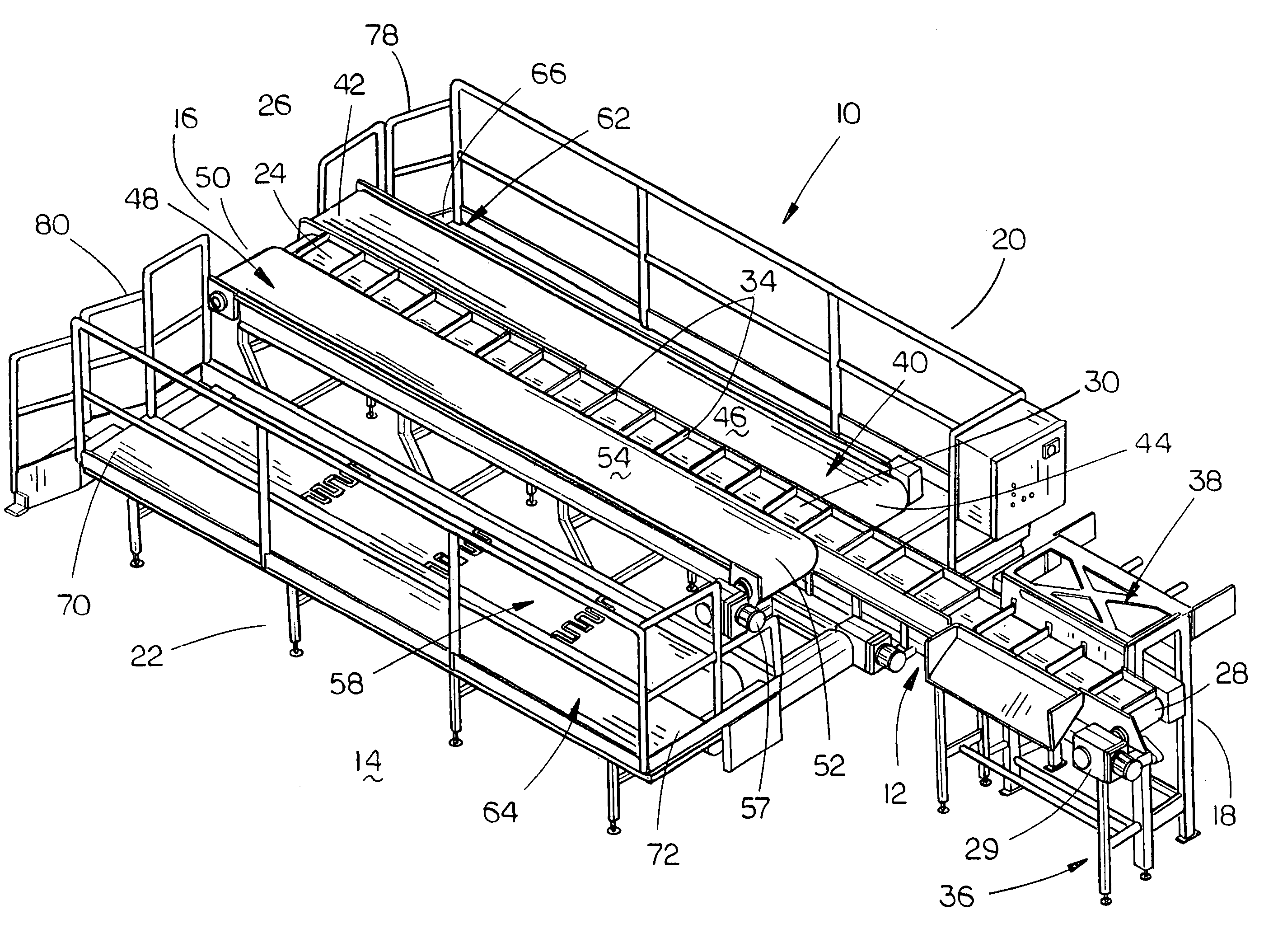
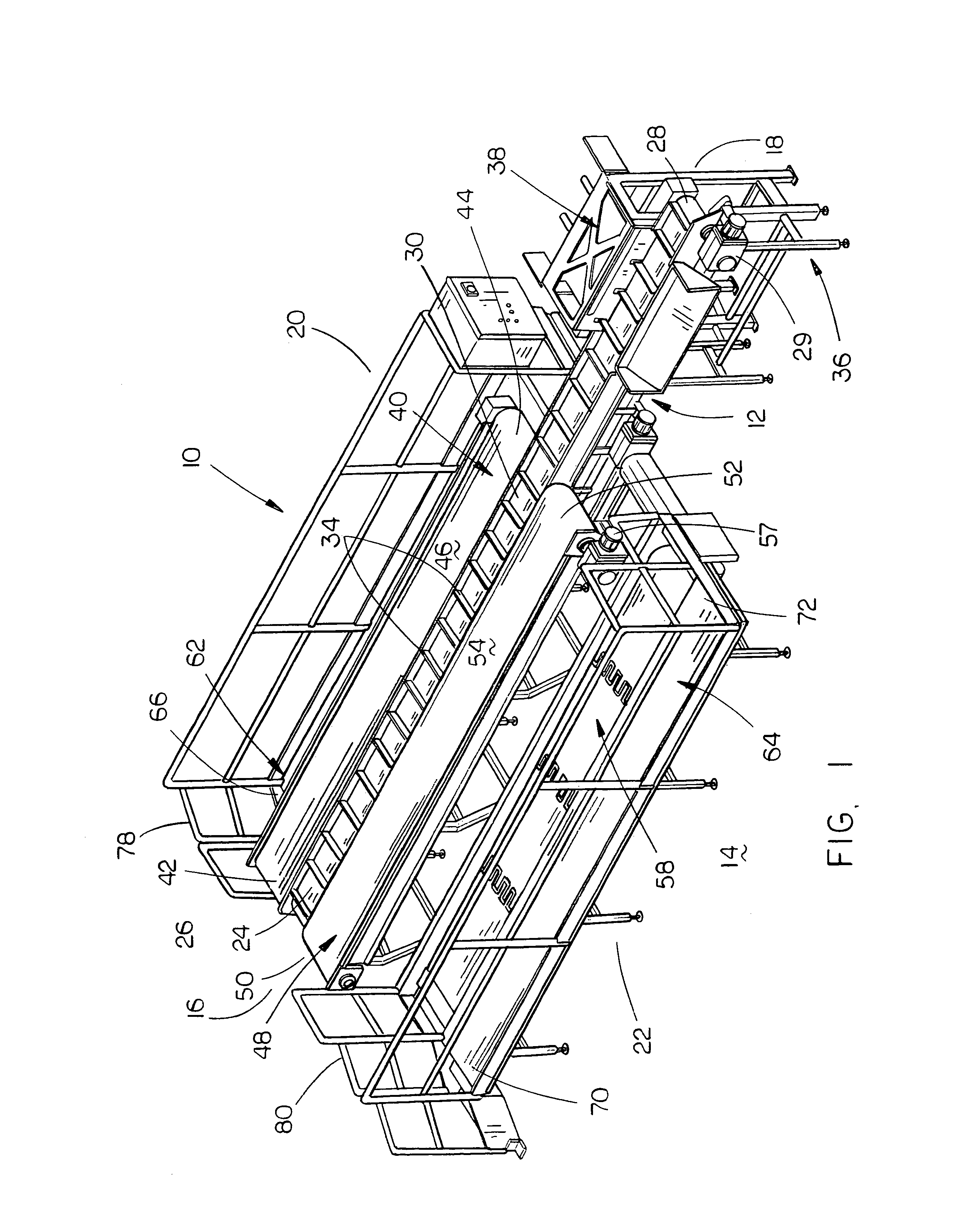
[0023]In the drawings, the meat processing conveyor system of this invention is referred to generally by the reference numeral 10. Although the system of this invention is ideally suited as a meat processing conveyor system wherein boning and trimming operations are performed, the conveyor system of this invention could also be used in other environments.

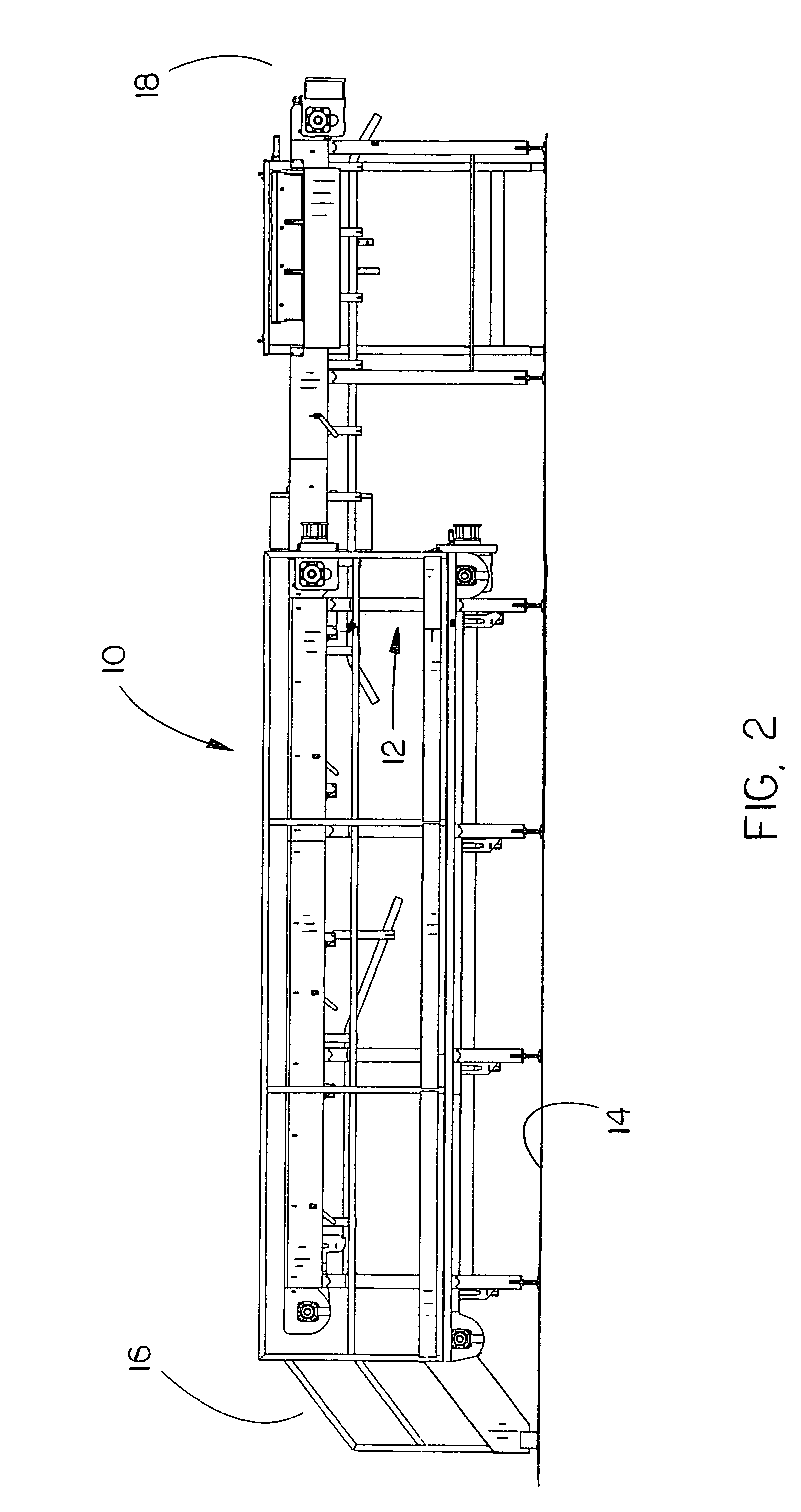
[0024]Conveyor system 10 includes a metal frame means 12 which is supported on a floor 14. For purposes of description, frame means 12 will be described as having a first end 16, a second end 18, a first side 20 and a second side 22.

[0025]The numeral 24 refers to a first elongated flat top modular conveyor belt of conventional design which has an infeed end 26 and a discharge end 28. Conveyor belt 24 is powered by a conventional electric motor 29 so that the carry portion 30 thereof travels from its infeed end 26 to its discharge end 28 and so that its return portion 32 travels from the discharge end 28 to the infeed end 26. Conveyo...


PUM


Abstract

A meat processing conveyor system wherein a first trim conveyor belt is positioned between first and second product conveyor belts. First and second personnel conveyor belts are positioned laterally of the first and second product conveyor belts respectively. First and second personnel walkways are positioned laterally of the first and second personnel conveyor belts respectively.

Description

BACKGROUND OF THE INVENTION[0001]1. Field of the Invention[0002]This invention relates to a meat processing conveyor system and more particularly to a meat processing conveyor system wherein a trim conveyor is positioned between a pair of product conveyors and which may also include a pair of personnel conveyors positioned adjacent the product conveyors. Still more particularly, the conveyor system of this invention may include personnel walkways, when the personnel conveyors are utilized, to enable the workers to return to the infeed end of the product conveyors after they have been moved to the ends of the product conveyors.[0003]2. Description of the Related Art[0004]In conventional meat processing conveyor systems wherein meat products are being cut, trimmed or removed from the original piece, a plurality of workers stand at one side or both sides of a product conveyor belt in a spaced-apart relationship and trim and remove products from an original piece of meat with each produ...

Claims


Application Information

Patent Timeline
IPC IPC(8): A22C17/00
CPCA22C17/0093
Inventor JAGER, TODD G.
Owner JAGER TODD G
Why Eureka
Try Eureka