System for transmission of electric power

a transmission cable and cable technology, applied in the direction of electric variable regulation, process and machine control, instruments, etc., can solve the problems affecting the maximum transmission length of the cable circuit, and achieve the effects of reducing power loss in operation, reducing power loss, and reducing power loss in construction

Inactive Publication Date: 2010-07-20
ABB RES LTD
View PDF29 Cites 5 Cited by
  • Summary
  • Abstract
  • Description
  • Claims
  • Application Information

AI Technical Summary

Benefits of technology

[0059]The principal advantage of the invention is that minimal power losses due to reduced dielectric and resistive losses mean that the length of an AC transmission cable reach according to the invention is not limited to around 50 km or so but may in fact be several hundred kilometers in length. This is so because the in the prior art method and system of shunt reactors to compensate for reactive power generation are only effective for a circuit lengths of up to 50 km or so as the resistance and impedance of the circuit is a function of the circuit length. For the invention, no reactive power is transmitted and so no shunt reactors are required to compensate, thus there is virtually no limit to circuit length caused by generation or transport of reactive power. This provides then AC power transmission cable systems with significantly lower power losses in operation that may link together power networks which are hundreds of kilometers apart in a way that is more economical to build than the Prior Art, which has to-have reactive power compensation equipment installed at least every 50 km or so.
[0060]Another advantage of the invention is that reactive power compensation by shunt reactors is not required at the ends of a transmission circuit or, even more disadvantageously, at intervals along the length of a prior art circuit. Instead, a transformer with wide transformation variability is required at each end of the circuit, and the circuit has to be operated with variable voltage. A transformer of some sort is almost always required at the end of a transmission circuit, so that an installation according to the invention is both less expensive to build and, with significantly lower power losses, less expensive to operate. Reactive power shunt reactors also have power losses associated with them.
[0061]For example, the power loss due to dielectric and charging power losses for an AC transmission cable under no-load are reduced by as much as one-third or more, which, when the number of many power networks that are run at no-load every night is taken into consideration, provides a great environmental and economic benefit. Further, in a particular embodiment of the invention a wide range transformer may only be required at one end of the transmission circuit.
[0062]Another advantage of the invention is that the thermal overload capacity of the cable in a transmission circuit described is greater than for Prior Art cable systems. This permits greater freedom in running under temporary overloads to ease problems in a power network.

Problems solved by technology

The problem with extending existing transmission cable installations is principally with generation and transport of reactive power.
Losses due to currents induced in the cable screen can also affect the maximum transmission length for cable circuits.

Method used


Image

  • System for transmission of electric power
  • System for transmission of electric power
  • System for transmission of electric power

Examples


Embodiment Construction

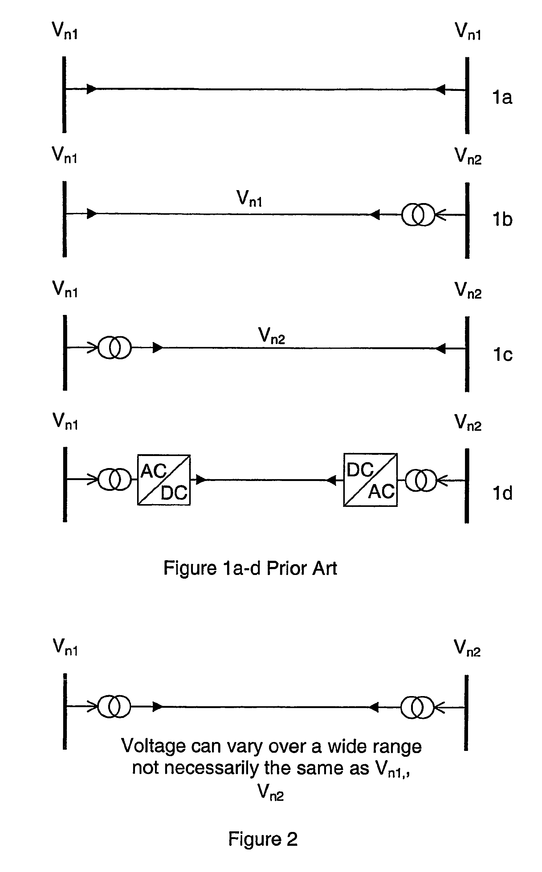
[0074]FIG. 1a (Prior Art) shows a HVAC transmission cable of which the nominal operating voltage Vn1 is the same at both ends of the line. If the nominal operating voltage at each end is not the same, Vn1≠V2, one possible Prior Art arrangement is shown in FIG. 1b, where the operating voltage for the cable is Vn1 and a transformer is installed at one end of the cable. FIG. 1c shows the same arrangement except for that the nominal operating voltage for the cable is Vn2. If the distance for AC transmission between terminal points is too great, HVDC technology may be used, as shown in FIG. 1d. In this Prior Art arrangement the problem of reactive power losses is overcome by rectifying from AC to DC current.

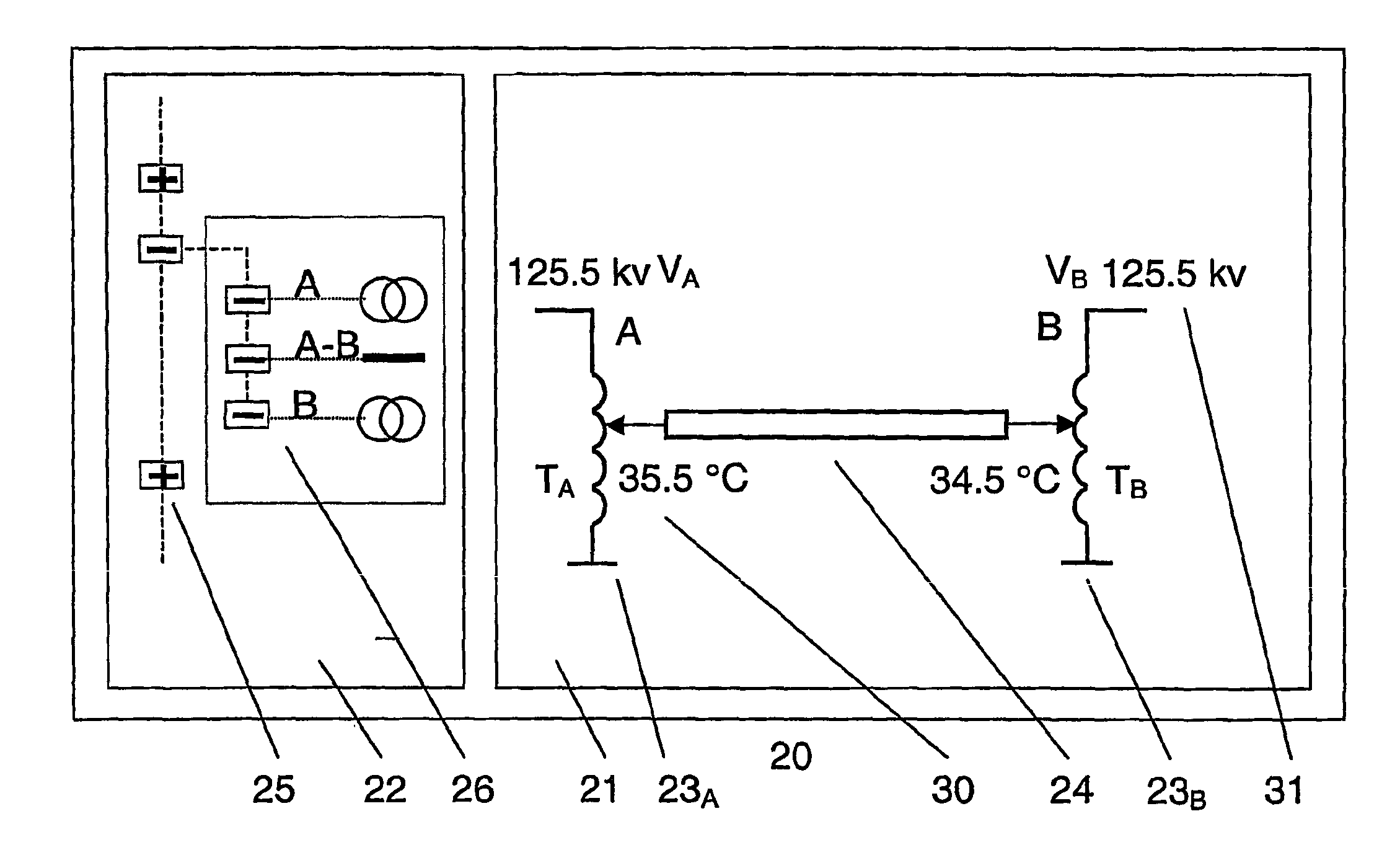
[0075]FIG. 2 shows an embodiment according to the present invention. It can be seen by comparing the invention of FIG. 2 to the prior art arrangements illustrated in FIGS. 1a-d that the cable voltage in the system according to the invention does not necessarily have to be the same as ...


PUM


Abstract

A high voltage AC transmission cable system for transmitting power between two points, each connected to one or more power networks, and a method to operate the system. At least one transformer is arranged at each end of the AC transmission cable, wherein at least one of the transformers is arranged to operate the transformer at a voltage whereby losses due to reactive power transport and dielectric losses are minimized. The AC cable is run at a variable voltage regulated such that the voltage is a function of the load for the transmission cable. This operating voltage is not necessarily the same as the nominal voltages in the connection points. A control and communication system and a graphical user interface for carrying out the method are also provided.

Description

CROSS-REFERENCE TO RELATED APPLICATIONS[0001]This application claims priority to Swedish patent application no. 0302574-9 filed 26 Sep. 2003 and is the national phase under 35 U.S.C. §371 of PCT / SE2004 / 001316.TECHNICAL FIELD[0002]The invention relates to AC transmission cable systems for power transmission within and between power networks. In particular, the system is concerned with minimising power losses associated with power transmission due to effects of reactive charging losses as well as resistive and dielectric losses.BACKGROUND ART[0003]Energy transmission by means of power cables is of particular importance applied in densely populated areas and when passing over stretches of open water. In densely populated areas land values, reliability and aesthetic factors have great importance whereas for passage over open water the costs of building large number of pylon foundations is what steers the choice towards cable solutions. The problem with extending existing transmission ca...

Claims


Application Information

Patent Timeline
Patent Type & Authority Patents(United States)
IPC IPC(8): G05F1/70H02JH02J3/18H02J3/22
CPCH02J3/18H02J3/22Y02E40/30
Inventor LINDAHL, STUREJOHANSSON, KENNETHFROMM, UDOJOHANSSON, STEFAN
Owner ABB RES LTD
Why Eureka
Try Eureka