
Cold forging apparatus and method for forming complex articles

Inactive Publication Date: 2004-05-13
TRAVIS RAY +1
View PDF4 Cites 5 Cited by
  • Summary
  • Abstract
  • Description
  • Claims
  • Application Information

AI Technical Summary

Benefits of technology

[0005] A further advantage of the apparatus and method of the present invention resides in the use of multiple machines which may be slower than the aforementioned cam operated cold headers, but which provide greater flexibility and backup in the event of a machine failure or down time for a more complex machine. In addition, cold forging apparatus in accordance with the present invention can be produced and sold at a competitive price. For example, it is presently estimated that the cost of a cold forging apparatus in accordance with the present invention is less than 25% of the cost of an automatic cam operated forging press. A still further advantage resides in the use of a computer program in conjunction with multiple sets of punches at a single station. It is also believed that the apparatus in accordance with the present invention will be less complex, less expensive to install, operate and maintain and more reliable than the automatic cam operated cold headers of the prior art. Recognizing, that the prior art automatic cam operated cold headers are capable of relatively fast speeds, it is believed that the use of two, three or more machines in accordance with the present invention will be capable of matching those speeds while providing many of the aforementioned advantages including costs and added flexibility.

Problems solved by technology

However, for more complex parts, the use of a multi station process requires duplication of equipment, additional set-up time, additional space, multiple dies and additional costs.
Such costs are particularly excessive for making a limited numbers of forged parts.
Such machines are capable of operating at high speeds, but are complex, expensive and require considerable set-up time before each run.
Accordingly, the use of such machines is generally limited to high volume items where the length of the run justifies the set-up time.
The use of such machines is also generally limited to parts which have sufficient complexity and sufficient market value to justify the costs of the machine, set-up time and other operating costs.

Method used


Image

  • Cold forging apparatus and method for forming complex articles
  • Cold forging apparatus and method for forming complex articles
  • Cold forging apparatus and method for forming complex articles

Examples


Embodiment Construction

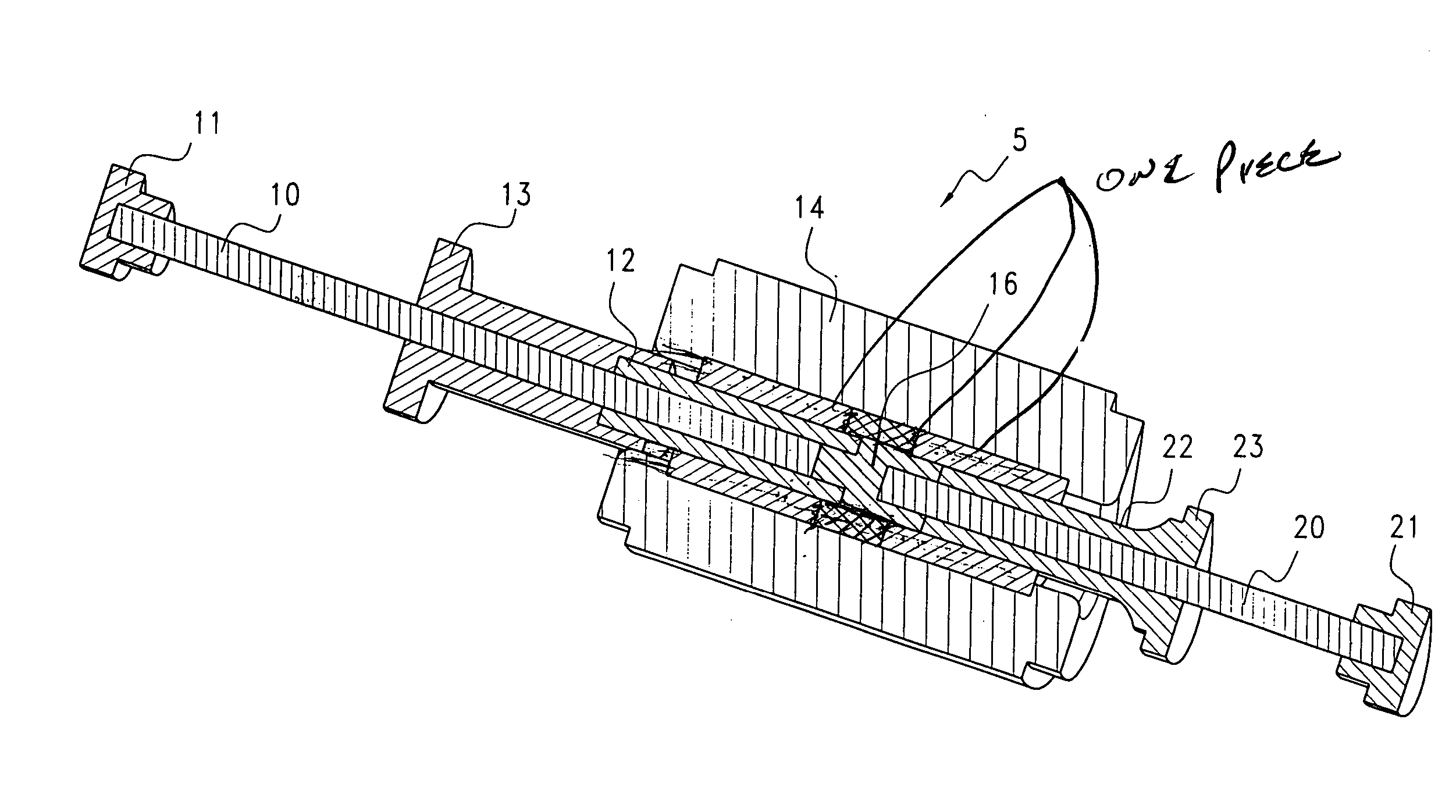
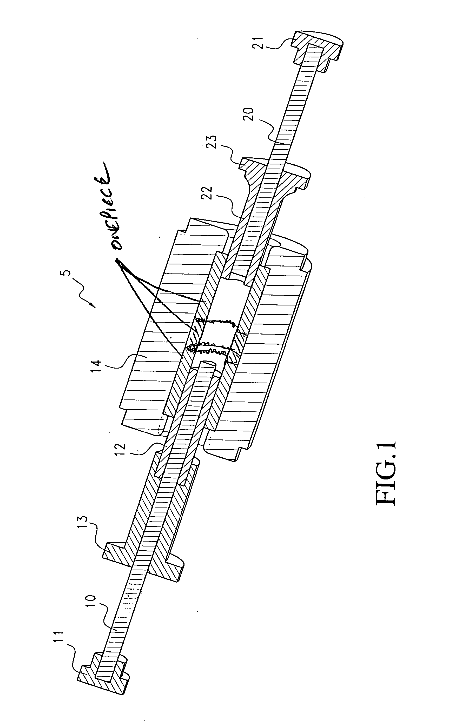
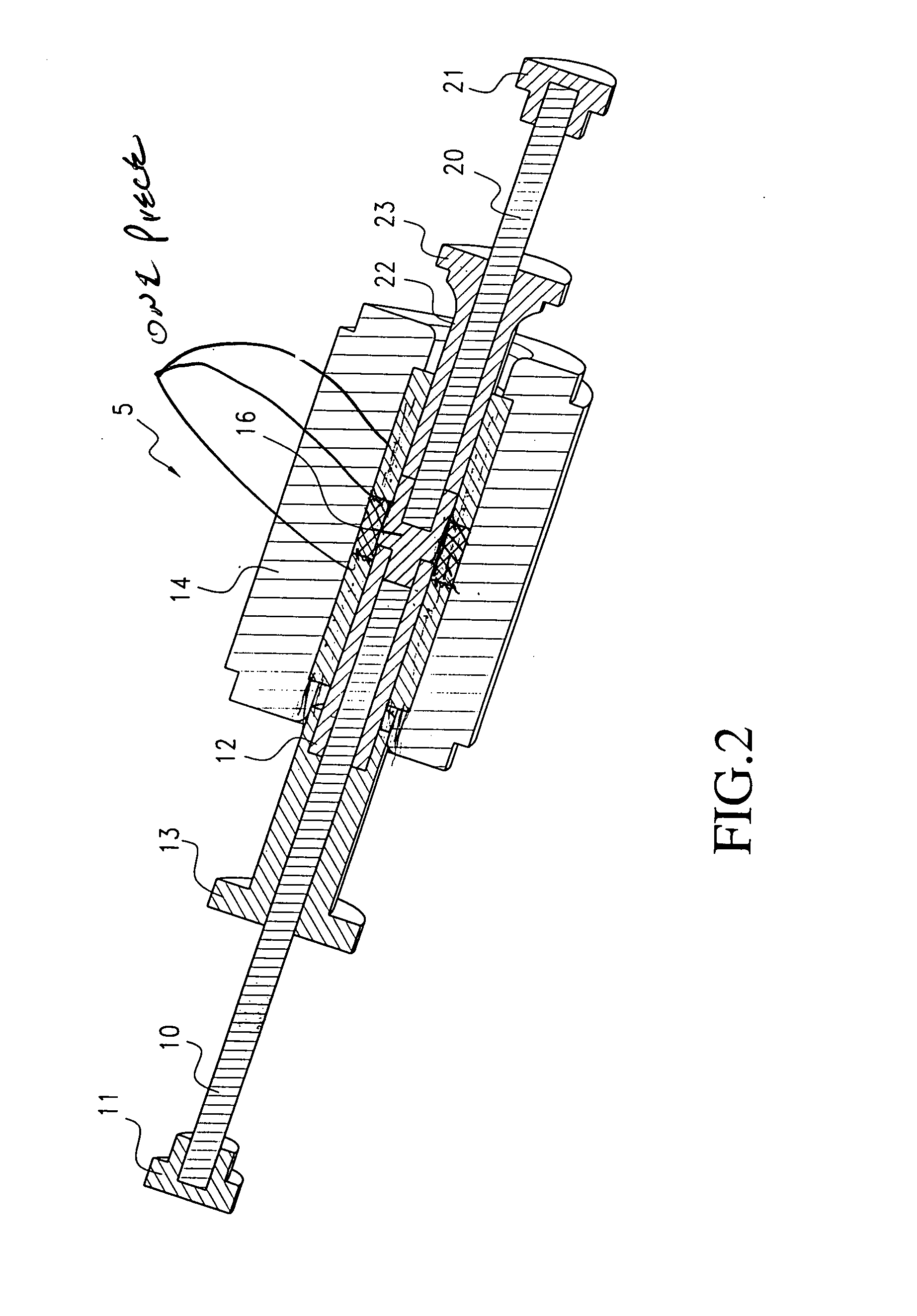
[0021] FIGS. 1 and 2 illustrate a portion of a cold forging apparatus in accordance with the present invention. As illustrated, a pair of coaxial confronting multiple punch assemblies are constructed and arranged to perform multiple functions or steps at a single station. As shown, a first multiple punch assembly includes a first inner punch 10 and a first outer punch 12 disposed on a common axis in a telescopic relationship so that each of the first inner punch 10 and outer punch 12 are separately controllable and free to move independently along the common axis. The punches 10 and 12 include enlarged end portions or driving elements 11 and 13, respectively, at one end thereof for applying force to each of the punches. The opposite ends of the punches 10 and 12 are shown within a die 14.

[0022] The second multiple punch assembly is similar to the first multiple punch assembly and includes a second inner or central punch 20 and a second outer punch 22 disposed on a common axis in a t...


PUM

PropertyMeasurementUnit
Pressureaaaaaaaaaa
Massaaaaaaaaaa
Shapeaaaaaaaaaa

Abstract

A cold forging apparatus for forming complex shapes at a single station includes a plurality of multiple function punch assemblies disposed on intersecting axes. Each of the multiple function punch assemblies includes an inner or a center punch and an outer or ring-shaped punch surrounding and in sliding contact with the inner punch. The apparatus also includes a die holder for positioning a mass or slug of metal between the punches. A computer system controls movement of the punches and is programmable to form parts of different shapes at a single station. Off axis punches and angularly offset punches and an additional punch or punch assembly are also disclosed.

Description

[0001] This is a Continuation-In-Part of our earlier filed U.S. patent application Ser. No. 10 / 291,361 which was filed Nov. 12, 2002. This invention relates to cold forging apparatus and methods for forming complex articles and more particularly to cold forging apparatus for performing multiple functions at a single station and to methods for forming complex metal shapes or articles at a single station.BACKGROUND FOR THE INVENTION[0002] Cold forging apparatus and processes are well-known. Such apparatus and processes have been used for many years in the commercial production of relatively simple parts at a single station or more complex parts with a multi station set up. However, for more complex parts, the use of a multi station process requires duplication of equipment, additional set-up time, additional space, multiple dies and additional costs. Such costs are particularly excessive for making a limited numbers of forged parts.[0003] More complex parts may also be forged in a mac...

Claims


Application Information

Patent Timeline
IPC IPC(8): B21C23/20B21C25/08B21J5/00B21J5/02B21J7/14B21J9/02B21J9/18B21J9/20B21J13/02
CPCB21C23/20B21C25/08B21J5/00B21J5/02B21J9/027B21J9/18B21J9/20B21J13/02B21J9/02
Inventor TRAVIS, RAYSTONE, PAUL
Owner TRAVIS RAY
Learn More